Prerequisite: Planning 2 or dean's permission
Units: 3.0
Classroom: online via Microsoft Teams
Class Time: Thursday: 9:30 AM-12:30 PM
Office Hour: Thursday: 12:30 PM -12:45 PM - Right after class time
Instructor: Zhuo Yao, Ph.D.
Instructor: Archt. Carmela C. Quizana
Thursday, November 24, and December 01, 2022
Instructor:Zhuo Yao Ph.D.
Instructor: Archt. Carmela C. Quizana
The design and planning of residential development is a significant component of any planning or urban design effort. Typically provided by private developers, residential development is primarily market-driven, with the housing types in a particular market dictated by a number of factors. Economic factors, such as cost of living, employment base, and disposable income, play a major role. Residential types will also vary greatly between regional markets,and often they will vary within a single municipal jurisdiction. Housing types acceptable in one locale may not be economically viable a short distance away.
In addition to economic factors, architectural style is perhaps the next greatest determinant in residential planning. Regional vernaculars, stylistic trends, climate, geography, local traditions, and other factors all affect the type of residential development proposed for a particular site.
ROLE OF HOUSING IN PLANNING AND URBAN DESIGN
Residential development creates a core citizenry around which communities are structured. Housing defines a population base that determines the location of schools, employment centers, and community facilities. Planners must be able to project long-term residential growth trends to provide adequate public services. Planners also need to understand trends in housing development. Due to continued advances in housing types, there is greater variety from which to create plans. The successful planner and urban designer will understand and support a wide range of residential development typologies.
COMMON TERMS
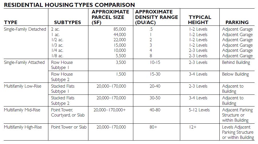
Because residential development is such a broad topic, it is important to have a common set of terms and classifications so as to avoid confusion. The five basic attributes of residential development are build- ing type, style, density, project size, and location.
Building Type
Building type refers to the arrangement of individual dwelling units and their placement next to, above, or below each other. “Single-family detached” and “multifamily attached” are examples of residential building types. Basic residential building types are described elsewhere in more detail in this section of this book.
Style Style refers to the architectural design of the dwelling unit. It is a subjective and qualitative attribute. “Contemporary,” “colonial,” and “prairie,” for example, are styles.
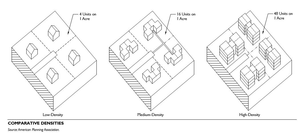
Density
Density refers to the number of housing units per area of land. The most common measure of residential density is dwelling units per acre (du/ac). Particularly for dense urban projects, density may be measured in floor-area ratio (FAR), which is the ratio of the gross building floor area to the net lot area of the building site. Density is commonly tied to location: densities are typically lower the further one moves from the city center. However, there are often variations in this pattern. New trends, for example, have seen relatively low-density urban infill projects replace obsolete higher-density multifamily housing, and relatively high-density, transit-based projects replacing large-lot residential development in the suburbs.
Project Size
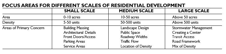
Project size refers to the land area of the project. This can range from a single-lot, 2,000-square-foot urban infill project to a 3,000-acre new community. Planners and designers must be conversant with the basic requirements of differing sizes of development.
Location
Location refers to the context of the project. This can range from rural greenfield sites to projects in established suburbs. It can also include urban brownfield sites, projects in well-established transit-based communities, and urban high-rises in a city center.
OTHER TERMS
Planners use other common terms to describe residential development:
Total project acreage: The total land area of a project
Net developable area: Total project acreage, minus open space and infrastructure acreage
Gross density: Number of residential units/total project acreage
Net density: Number of residential units/net developable area
RESIDENTIAL TYPES
Residential types can be classified into five basic categories:
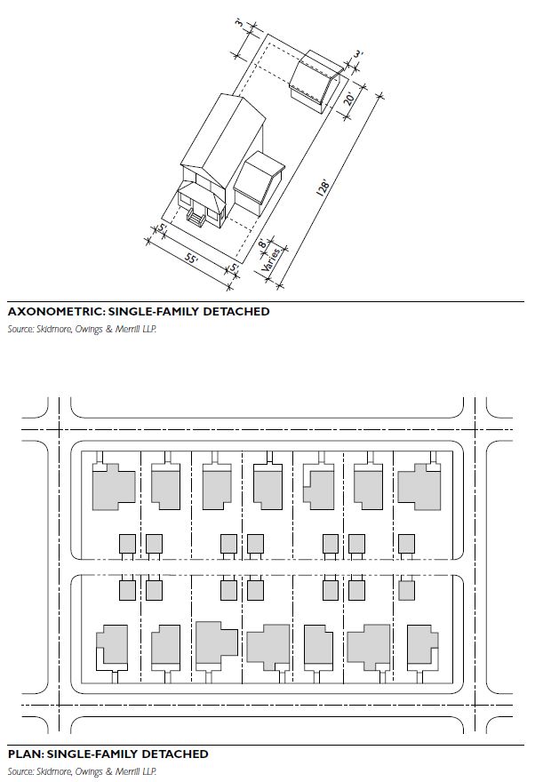
Single-family detached. Single-family detached dwelling units are physically separated from the units immediately adjacent to them.
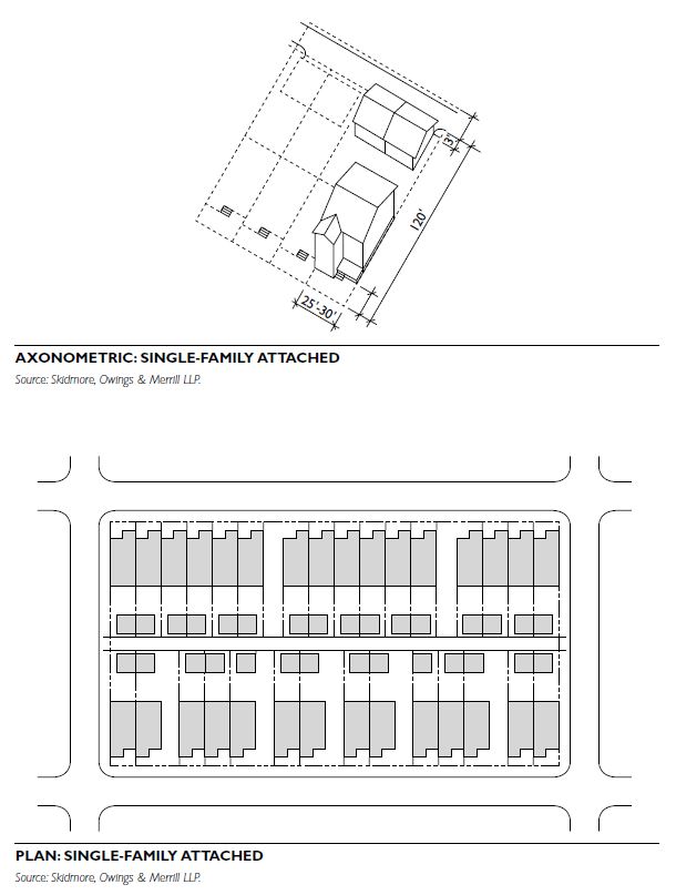
Single-family attached. Single-family attached dwelling units share common walls with units laterally adjacent to them.
Multifamily low-rise. Multifamily low-rise developments have dwelling units that share common walls with the units that are laterally and vertically adjacent. They typically range from two to four levels in height, with multiple service cores and either structured or surface parking.
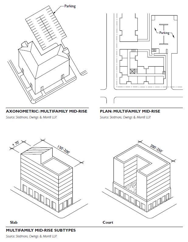
Multifamily mid-rise. Multifamily mid-rise dwelling units share common walls with the units that are laterally and vertically adjacent. They are generally 5 to 12 levels in height, with a common core. They sometimes include structured parking.
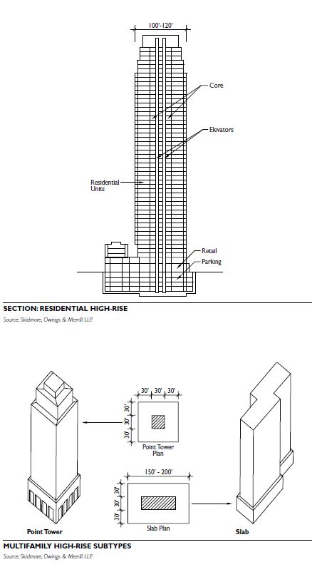
Multifamily high-rise. Multifamily high-rise dwelling units share common walls with the units that are laterally and vertically adjacent. They are generally 12 to 50 or more levels in height, with a common core, and often include structured parking.
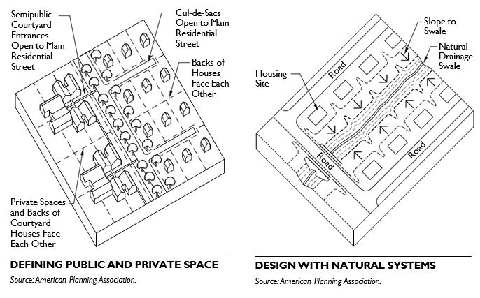
SITE PLANNING CONSIDERATIONS
Zoning Classification
Zoning typically determines the density of residential development. In addition to density, zoning may also dictate height limits, required planted area, massing criteria, and allowable ancillary uses. Planners must know the zoning under which a plan is to be evaluated or created and the relevant zoning constraints.
Infrastructure Design
A major component of a residential development is infrastructure. This primarily includes roads, utility easements, and other rights-of-way, but also may include other elements such as accommodations for public structures. Infrastructure may use 10 to 30 per- cent of a project’s gross land area.
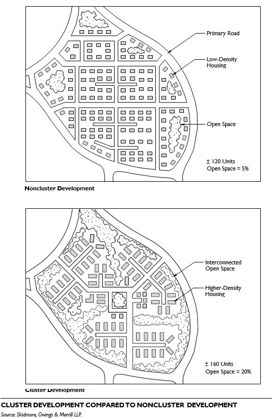
Open Space
Open space includes parks, plazas, greenways, stormwater management areas, and any other unpaved or undeveloped areas. Open space may use 10 to 30 percent of a project’s gross land area. Where conservation is a goal, this percentage may increase.
Setbacks
Often contained within the zoning code, and closely linked to density and massing considerations, set- backs include front, rear, and side-yard setbacks. When density is higher, setbacks are typically smaller. Urban conditions may not require setbacks.
Allowed Density
Density is often the primary determinant in the physical layout and appearance of a project. It will influence the housing type and perhaps the style of the project. Densities are calculated in dwelling units per acre (du/ac), and can range from 1 du/10 ac for a rural lot to 100 du/ac for an urban high-rise. Typical densities range from 1 du/ac for single-family detached homes to 20 du/ac for townhomes.
Parking
For many residential projects, parking must be provided within or adjacent to each dwelling unit. For higher-density projects (above 20 du/ac), common parking facilities are created adjacent to the residential structure. The number of parking spaces per unit is driven either by regulatory requirements or by market desires. The number of parking spaces required per dwelling unit significantly affects site planning with important economic and design con- sequences. Planners and developers should carefully examine the standards used to determine the appropriate number of parking spaces for a use; practice has been to require too much parking in many cases.
Restrictions on Ancillary Structures
Zoning may dictate restrictions on ancillary structures, such as garages or dwelling units. Recent practice has indicated a trend of accessory living units near or attached to the main structure. Codes that do not allow ancillary units should be revised to accommodate them to provide affordable housing alternatives and “aging in place.”
BUILDING PLANNING CONSIDERATIONS
Orientation
The direction in which a residential unit or project is oriented should be considered. This will affect potential solar gain. It also affects light penetration into units, as well as solar exposure for outdoor areas such as patios and courtyards.
Entry
Clear access to and identity of primary building entries must be carefully considered. Buildings and units should have a distinct main point of entry, usu- ally identifiable from a public way. Avoid primary entrances from parking structures or other ancillary elements.
Massing
The size and shape of residential structures individually and their arrangement relative to each other are primary urban design considerations. Massing is a major consideration in determining how a building or group of buildings will relate to the surrounding con- text. Zoning regulations (height and bulk) and design guidelines can be used to address problems related to development mass that is out of scale with neighborhood or community character.
Design Guidelines
Traditionally, design guidelines have been “use- based,” dictating acceptable uses and densities. While this approach is still appropriate in some instances, increasingly design guidelines have become “form- based,” concentrating more on aesthetic and form issues.
PLANNING AND DESIGN SEQUENCE
The planning and design sequence for residential development follows this general process:
Programming. Clarify the number of units, typical square footage of units, and sizes of other physical elements of the project.
Opportunities and constraints. Delineate all physical opportunities and constraints present on the site, especially qualitative constraints, such as views, natural features, and adjacent uses.
Site plan testing. Delineate all development pro- gram elements, overlaid with code and site constraints. Reconcile incompatibilities.
BEST PRACTICE PRINCIPLES
Regional Vernacular
Residential development should be sensitive to regional issues, including climate, materials and methods, and regional styles and traditions. Residential style often reflects the region in which it is constructed.
Mixed-Use
Mixed-use development includes a variety of uses within a project, such as neighborhood commercial retail in portions of a residential project. Mixed-use development also helps provide basic services (e.g., dry cleaners; food store; drug store) to residents, increases design options, and creates opportunities for pedestrian-oriented design.
Transit-Oriented Development
Recent planning trends include a return to higher- density housing located adjacent to transit lines, which increases transportation alternatives for residents and allows for reduced automobile dependency and parking requirements.
COMMON SUBTYPES
Single-family detached units come in many forms. The most prevalent subtype is the stand-alone house. Another subtype is zero-lot line housing, where there is no setback from the property line and the structures do not share common walls.
PROJECT SIZE
Lot sizes typically vary from 1/8-acre (0.5-hectare) lots (approx. 5,500 square feet) to 2-acre (0.81-hectare) or larger lots.
ASPECT RATIO
Typical single-family lots will have a width-to-depth ratio of 1:2. Lot widths are typically multiples of 10 feet (3.1 meters), and can range from 30 feet (9.3 meters) to 100 feet (30.48 meters).
SETBACKS
Setback requirements are typical for single-family detached lots and will apply to front, rear, and side yards. Typical setbacks range from 5 feet (1.55 meters) to 20 feet (6.2 meters), with front-yard set- backs greater than side-yard setbacks by a ratio of 2:1. Rear-yard setbacks are typically similar to side- yard setbacks, but may be reduced if an alley condition exists.
VEHICULAR ACCESS
While vehicular access is often from the front of the lot, recent trends encourage planners and developers to consider alleys for vehicular access, where possible.
COVERAGE
Some zoning classifications may place restrictions on the percentage of the site area that can be covered by the building footprint.
MASS AND VOLUME
Some zoning classifications may restrict the height and bulk of structures. Design guidelines or historic overlay districts may restrict the volume and shape of the structure.
ORIENTATION
Structures should be oriented to take advantage of solar exposure and prevailing winds, and toward the primary street on which they are situated.
PARKING Parking is commonly provided within the lot, typically in garages accessed from rear alleys or streets.
COMMON SUBTYPES
Single-family attached units come in many forms, including duplexes and townhomes. Many town- home variations have emerged as a result of market forces and regional vernacular styles.
PROJECT SIZE
Project sizes vary from 1/12-acre lots (approx 3,500 square feet or 325 square meters) to 1/5-acre lots (approximately 8,000 square feet or 743 square meters).
ASPECT RATIO
Typical single-family attached lots will have a width- to-depth ratio of 1:4. Lot widths are typically multiples of 5 feet (1.5 meters), and can range from 20 feet (6.1 meters) to 40 feet (12.2 meters).
SETBACKS
Setback requirements are typical for the front and rear of single-family attached lots. Typical setbacks range from 5 feet (1.5 meters) to 20 feet (6.1 meters). Rear-yard setbacks are similar to front-yard setbacks, but may be reduced if an alley condition exists. For duplex structures, the setback on the side yard that is not attached will vary.
VEHICULAR ACCESS
For single-family attached housing, vehicular access to the garage is typically from alleys at the rear of the lot. In suburban conditions, some attached homes have garages in front or side of the unit.
COVERAGE
This type of housing will typically have a higher degree of site coverage than single-family detached. Restrictions may still be placed on the overall site coverage of an individual lot, and project wide provisions may need to be made for stormwater management.
MASS AND VOLUME
This type of housing will typically be taller than sin- gle-family detached units, due to smaller lots, parking underneath, or other factors. While most units are two or three levels, occasionally four- and even five- levels units are in use. For taller structures an elevator may be provided in the unit. Some zoning classifications may restrict height and massing of structures.
ORIENTATION
Structures should be oriented to take advantage of solar exposure and prevailing winds, and toward the primary street on which they are situated. More than any other type of housing, single-family attached structures should also be oriented to enhance privacy between units, especially on dense urban lots.
PARKING
Single-family attached units are often provided with an attached garage immediately adjacent or under the dwelling unit, or may have adjacent surface parking.
COMMON SUBTYPES
Multifamily low-rise is perhaps the most diverse housing type. Subtypes include garden apartments and courtyard apartments.
PROJECT SIZE
Multiunit buildings typically occupy one lot, collectively controlled through condominium ownership or by a single property owner. The number of units and zoning regulations determine the overall building size.
ASPECT RATIO
Multifamily residential development projects are extremely flexible in terms of lot configuration and proportion. They may occupy relatively narrow, deep lots, or shallow, wide lots. Due to the inherent flexibility of unit configurations, building designs can adjust to many parcel variations.
SETBACKS
While setbacks for this type of residential use can vary greatly depending on the urban context, multifamily low-rise buildings are often subject to greater setbacks than lower-density housing because of larger building footprints and three- to four-level building heights. Zoning restrictions dictate specific setbacks.
VEHICULAR ACCESS
Principal access may be from a major public street or from streets and driveways internal to the development. Access to parking can occur from the front, rear, or side yards. Drop-off areas for principal entries should be oriented to the primary addressing street.
COVERAGE
This type will typically have a higher degree of site coverage than single-family attached. Restrictions may still be placed on the overall building site coverage, and projectwide provisions may be required for stormwater management and open space.
MASS AND VOLUME
This type will vary from two to four stories in height. Flexible unit configurations allow corresponding flexibility in massing and volumetric configurations. This type allows a great variety of massing solutions.
ORIENTATION
Orientation of this type is primarily dictated by site configuration and access to primary streets, though solar orientation may be a consideration. Due to larger building footprints, there may be orientation constraints on steep or hilly terrain.
PARKING
Parking is provided either within or immediately adjacent to the structure. In urban conditions, a parking structure may be provided beneath or next to the building.

COMMON SUBTYPES
Because of the vertically oriented, repetitive qualities of multifamily mid-rise, this type has a limited number of variations.
PROJECT SIZE
Multiunit buildings typically occupy one lot, collectively controlled through condominium ownership or by a single property owner. The number of units and zoning regulations determine the overall building size.
ASPECT RATIO
Due to the presence of a building core, and thus a relatively large footprint, this type requires fairly regularized parcels with an aspect ratio ranging from 1:1 to 1:2.
SETBACKS
While setbacks for this type vary greatly depending on the urban context, because of larger building footprints and 5- to 12-level building heights, multifamily mid-rise buildings may be subject to greater building setbacks than lower-density housing. Zoning regulations will dictate specific setbacks.
VEHICULAR ACCESS
Principal access may be from a major public street or from streets and driveways internal to the development. Access to parking can occur from the front, rear, or side yards. Drop-off areas should be oriented to the primary addressing street.
COVERAGE
This type will typically have a site coverage range of 40 to 60 percent, though this may increase to 80 to 90 percent in urban conditions. Zoning will dictate the specific site coverage of a building, and projectwide provisions may be required for stormwater management and open space.
MASS AND VOLUME
This type will vary from 5 to 12 stories in height. Repetitive floor configurations with a building core will drive overall massing. Variations in building shape and form can be obtained through volumetric variations and manipulation of external cores and unit configurations.
ORIENTATION
Orientation of this type is primarily dictated by site configuration and access to primary streets, though solar orientation may be a consideration. Due to larger building footprints, there will be some orientation constraints on steep or hilly terrain.
PARKING
Parking is provided either within or immediately adjacent to the structure. Due to the number of units in the building, a parking structure is typically required.
COMMON SUBTYPES
Because of the vertically oriented, repetitive qualities of the multifamily high-rise, this type has a limited number of variations.
PROJECT SIZE
Multiunit buildings typically occupy one lot, collectively controlled through condominium ownership or by a single property owner. The number of units and zoning regulations determine the overall building size.
ASPECT RATIO
Due to the presence of a building core, and thus a relatively large footprint, this type requires regularized, rectangular or square parcels with an aspect ratio ranging from 1:1 to 1:2.
SETBACKS
While setbacks for this type can vary greatly depending on the urban context, multifamily high-rise buildings may be subject to greater building setbacks than lower-density housing because of larger building footprints and 12- to 50-plus-level building heights. Zoning will dictate specific setbacks.
VEHICULAR ACCESS
Principal access may be from a major public street or from streets and driveways internal to the development. Access to parking can occur from the front, rear or side yards. Drop-off areas and building front door should be oriented to the primary addressing street.
COVERAGE
This type will typically have a site coverage range of 40 to 60 percent, though this may increase to 80 to 90 per- cent in urban conditions. Zoning will dictate the specific site coverage of a building, and project wide provisions may be required for stormwater management.
MASS AND VOLUME
This type will vary from 12 to 50-plus stories in height. Repetitive floor configurations with a building core will drive overall massing. Variations in building shape and form will typically be in façade manipulation, though some volumetric variations can be obtained through core and unit manipulation. Tower floorplates may decrease in size as building height increases.
ORIENTATION
Orientation of this type is primarily dictated by site configuration and access to primary streets, though solar orientation may be a consideration. Due to larger building footprints, there will be some orientation constraints on steep or hilly terrain.
PARKING
Parking is provided either within or immediately adjacent to the structure. Due to the number of units in the building, a parking structure will almost always be required. Reduced or shared parking is increasingly common.
Factory-built housing describes any structure designed as a residential dwelling that is built primarily off-site from the building site. Factory-built housing consists of three main types: manufactured homes, modular homes, and mobile homes. Panelized and precut homes can also be included in this category.
Nearly 25 percent of all new single-family housing starts are manufactured homes. Affordability is a key factor in the growth of manufactured housing. Manufactured housing can cost from 10 to 35 percent less than traditional site-built housing, due in part to the factory-built process. Manufactured homes are constructed with the same materials as any other site- built residential structure; therefore, the durability of these dwellings is equal to those constructed on-site.
MANUFACTURED HOME TYPES
There are two basic types of manufactured homes, single-section and multisection. The number of units in the structure also defines them.
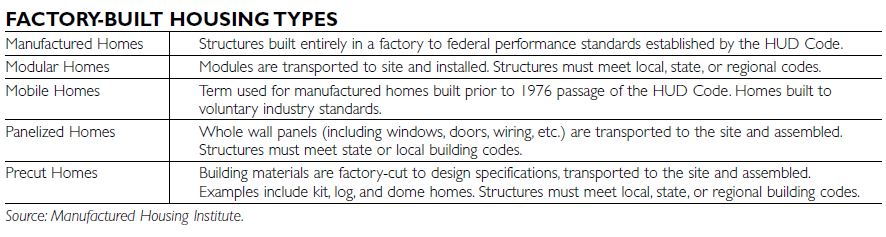
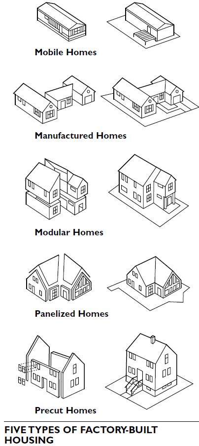
Single-Section Homes
Single-section homes are structurally complete once they leave a manufacturing facility. They can be one- or two-story structures.
Multisection Homes
Multisection homes consist of two or more sections that are assembled or completed at the building site. Multisection homes are used in two-story designs.
Multiunit Configurations
In addition to multistory configurations, manufactured homes can also be used in multiunit configurations. These units consist of a number of different manufactured sections that are then assembled on-site as duplexes, fourplexes, or townhomes.
REGULATION
Unlike other site-built structures, manufactured home construction is regulated at the federal level.
HUD Code
All manufactured homes are built to the Federal Manufactured Home Construction and Safety Standards. Commonly referred to as the HUD Code, it is the only federally regulated national building code. The HUD Code sets standards for heating, plumbing, air conditioning, thermal and electrical systems, structural design, construction, transportation, energy efficiency, and fire safety. Originally enacted in 1976, the code was revised in the early 1990s to enhance energy efficiency, ventilation standards, and wind resistance. Every manufactured home is issued a label, after inspection, certifying that it was built in compliance with the HUD Code.
The Manufactured Housing Improvement Act, adopted in 2000, provides for more timely updates to the HUD Code. It also requires each state to establish an installation program. On-site additions, such as garages or porches, are not regulated by the HUD Code and must be built to local, state, or regional building codes.
State and Local Regulation
Although federal law regulates how manufactured homes are built, state and local laws still govern where manufactured homes can be sited. Local regulation of manufactured homes is based on state law. State laws regulating manufactured homes vary widely, from failure to address the issue at all to mandating that the structures be allowed as a matter of right on any land zoned for single-family housing.
SITE CONSIDERATIONS
It is essential that access to the building site be unobstructed, because manufactured homes are transported in large, oversized components. Narrow streets, utility lines, trees, fences, and steep terrain can all impose challenges. Advances in installation equipment and technology have made previously difficult sites more accessible, however. Manufactured homes are typically placed relatively close to the ground. This type of siting involves excavation within the foundation walls to make room for the steel and wood floor assembly. Care should be exercised to make sure that the site drains properly, including from within the foundation walls. In some cases, the architectural context may require a different type of siting, if additional vertical mass is preferable.
DESIGN CONSIDERATIONS
When constructing or modifying a home, regardless of the type of construction, evaluate the physical surroundings into which the home will be incorporated. Once known primarily for providing rural housing, manufactured homes have evolved with new architectural styles that blend into most neighborhoods. Exterior designs make these homes virtually indistinguishable from site-built homes. Technology advancements now allow for interior ceiling heights to reach up to 9 feet. Also, new “hinged-roof” systems have made it possible to produce homes with pitched roofs like their site-built counterparts. The single most important advancement in the industry in recent years has been the development of two-story models.
An increasing number of jurisdictions are permit- ting manufactured homes by right in existing communities when certain unit design and siting specifications are met. Essential characteristics and appearance standards include roof material and pitch, siding, shape and orientation of home, elevation, foundation, entrance, and landscape design. In order to achieve true visual compatibility with existing neighborhoods, many manufactured homes are modified or enhanced on-site. Consider such upgrades carefully and equitably so as not to affect affordability of homes or favor one type of construction over another.
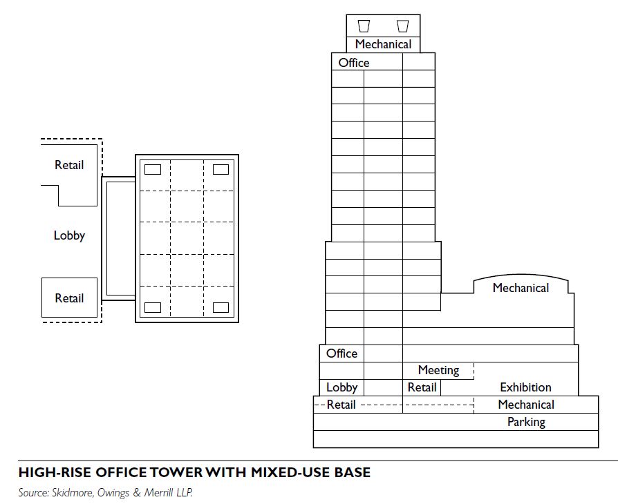
Office buildings are structures designed primarily as places for work, commerce, or research, and characterized by the following attributes:
Office buildings may range in height from 1 level to 50 or more levels, with a floorplate ranging from 10,000 to 50,000 square feet. Population density, lease span, daylight requirements, and cost of land all influence building form. Building shape and size is dictated primarily by commercial forces, architectural design, and zoning constraints.
Because of the prevalence of office buildings throughout the world and the relatively common design parameters that influence their form, the office building is one of the most thoroughly understood building types. The economics of planning, constructing, and owning office buildings have been extensively documented and analyzed, creating commonly accepted precedents for their design and construction.
BASIC OFFICE BUILDING TYPES
Office buildings are primarily of two economic types: speculative, where the end user is not defined, and build-to-suit, where the end user is known. For planning purposes, office buildings can be divided into three categories: low-rise, mid-rise, and high-rise.
Low-Rise Office
Mid-Rise Office - Four- to 12-level structure. - Found in urban and suburban conditions. - Most prevalent of office building types. - Adaptable to varied site configurations and sizes. - Typically served by structured parking.
High-Rise Office - Thirteen to 50 or more levels. - Found primarily in dense urban conditions. - Due to economic constraints, high-rise buildings rarely are exclusively for office uses.
Special Types In addition to the basic types, there are many specialized office building types that have evolved to meet specific functional requirements.
Research and development (R&D)/high-tech. Typically a low-rise office building dedicated to research and development of various types.
Medical office. Typically a mid-rise office building with an above-average (30,000 to 50,000 square feet) floorplate, dedicated to medical- related functions. It may require specialized equipment, including wet risers (vertical shafts or chases), extensive lab equipment, and waste disposal.
Exhibition/trading. Typically located within the base of a larger building, but occasionally a distinct building unto itself. This type has a very expansive (40,000 to 80,000 square feet) floor- plate and open floor plan, and is used for functions requiring large open areas. Cores are located at the perimeter of the space.
BUILDING PLANNING CONSIDERATIONS
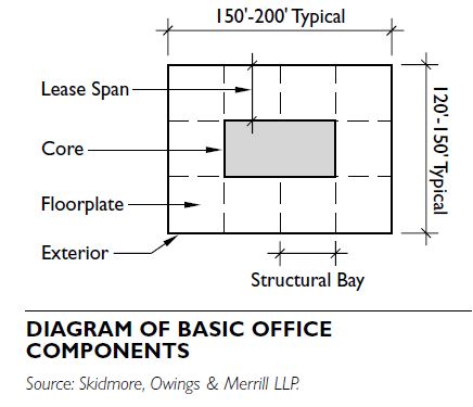
The architectural organization of office buildings consists of three components:
The variation of configurations of these three elements can be extensive. Core Location
There are three common core configurations:
Planning Module
The planning module of an office building is 5 feet. This can be either multiplied to achieve general building dimensions or subdivided to determine detailed dimensions.
Floorplate
A typical floorplate in the United States is approximately 20,000 square feet, but can range up to 50,000 square feet. Special conditions, such as trading floors, can increase this dimension even further. If natural light requirements apply, smaller floorplates may result.

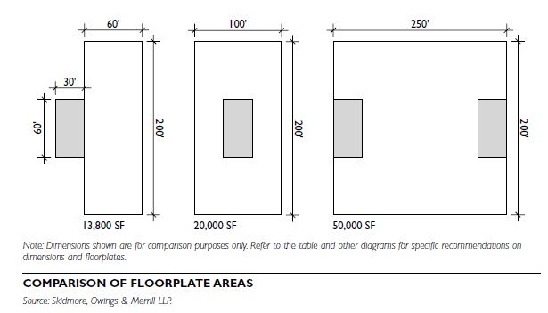
Lease Spans
The lease span is the distance from the edge of the core to the exterior wall. Typical U.S. lease spans, which are defined in multiples of 5 feet, include:
Elevator
Elevators are ubiquitous features of office buildings. Smaller buildings may have three to four elevators, while office towers may have 20 to 40 elevators. Taller buildings often have “zoned” elevators that serve particular zones or groups of floors, expediting travel.
General criteria include:
Dictated primarily by economics, and secondarily by functional and aesthetic issues, floor-to-floor height affects the square footage of exterior wall, which affects overall costs.
DESIGN GUIDELINES
Design guidelines can positively affect the aesthetic and functional aspects of a building or series of buildings. Most useful on urban sites or in office parks, design guidelines can provide control for building height, entry location, service locations, building materials, and other aesthetic concerns. Urban and Suburban Office Buildings Office buildings are found in both urban and suburban locations. Urban office buildings typically occupy sites ranging from 20,000 to 60,000 square feet (1,858 to 5,574 square meters; or 0.5 to 1.5 acres; or 0.2 to 0.6 hectares). They can be serviced from alleys, if they are present, discrete loading docks adjacent to the street, or underground service areas. Parking is usually underground or on the lower levels of the building.
Suburban office buildings typically occupy larger sites, ranging from 80,000 to 400,000 square feet (7,432 to 37,161 square meters; or 2 to 10 acres; or 0.81 to 4.04 hectares). The larger site allows more landscape planted areas, larger service areas, and surface parking. Some moderate-density suburban office buildings may have two to three levels of structured parking. One suburban application of the office building is in groupings of multiple buildings, commonly known as office parks, which are usually developed and controlled by one entity. Office parks are addressed elsewhere in this book.
SITE PLANNING CONSIDERATIONS
Zoning
Zoning will control overall site development, including density, height, and setbacks.
Site Constraints
Site constraints include easements, height limits, density limits, road access, curb-cuts, wetlands, floodplains, and any other elements that reduce or otherwise modify buildable area.
Density
Commonly measured in floor-area ratio (FAR), which is the total square footage of the building divided by the total square footage of the site, density deter- mines the overall square footage allowed. Below-grade area, parking, and some mechanical areas typically do not count against allowable FAR.
Site Organization
For a typical suburban condition, planners should estimate one-half of the site for surface parking, one
fourth of the site for the building footprint, and one fourth of the site for landscape. As the density of the development increases, the percentage of the site devoted to parking and landscape planting decreases.
Circulation
Circulation includes three primary considerations: site entry and building drop-off, parking ingress and egress, and service access.
Parking
Parking is typically calculated as a number of parking spaces per 1,000 square feet of building area. Check applicable zoning and parking regulations to deter- mine specific requirements. Parking credits may be given for transit-oriented development.
Service
Service access is typically located under, within, or immediately adjacent to the building. Due to the types of activities in an office building, service requirements are relatively minimal. Service areas typically require about 5,000 square feet (464.5 square meters), thought this will vary depending on specific uses and building size.
Planted Areas and Open Space
Planted areas and open space serve two primary functions for an office building site:
Planted areas can also screen the building from adjacent uses, and provide some recreational benefit to the building occupants. Local regulations will dictate the precise amount of open space required on a particular site, which can be as high as 40 to 50 percent of total site area.
PLANNING AND DESIGN SEQUENCE
The general planning and design sequence for office buildings is as follows:

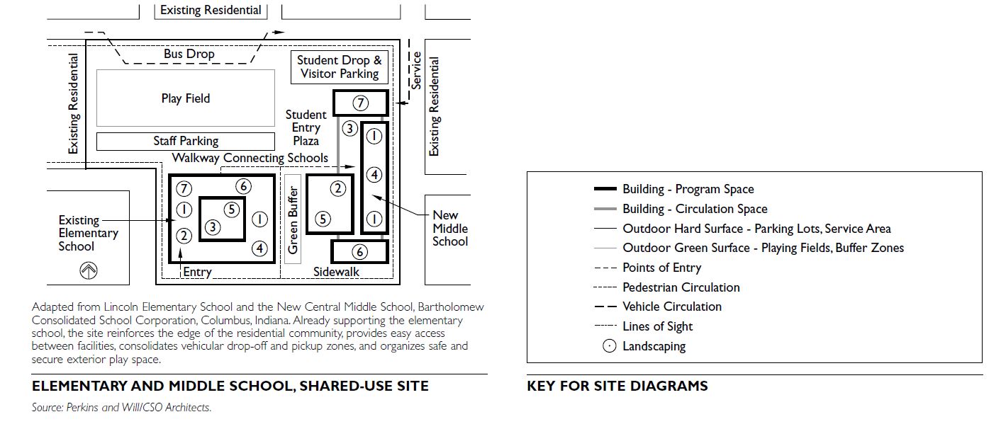
The primary purpose of a school is to provide a place conducive to the learning experiences of the youth who attend the school. Placing schools close to the heart of the communities they serve decreases automobile usage and commuting time. Schools built within a community can also leverage opportunities to enter into partnerships with local libraries, theaters, arts centers, and recreational facilities.
BUILDING CONFIGURATIONS
Elementary schools in the United States do not have a standard building configuration by grade level; almost any sequential combination of grades may occur. Configurations might include several grades collected in one building. For example, prekindergarten to second-grade buildings might be followed by third- to fifth-grade buildings and sixth- to eighth-grade buildings. Individual school districts determine building configurations and can be based on many factors, including the determination of how best to meet the individual needs of the students in the district.
Middle and high schools may also be configured in a variety of arrangements. Most common perhaps are middle schools with sixth to eighth grades and high schools with ninth to twelfth grades; however, sixth to twelfth grades, tenth to twelfth grades, and other configurations can be found. Magnet programs, alter- native schools, and schools with a special curricular focus can all influence the configuration of grades with the building.
SITE SELECTION
Siting a school facility is an important community decision and should be consistent with the community’s adopted comprehensive plan.
When selecting a new school site, preference should be given to in-town sites to maximize the proportion of students who can use safe routes to school on foot or by bicycle. Apart from demographic considerations of population and proximity to other facilities, consideration must also be given to the following:
Selection criteria for middle and high school sites may be broadened by the need to house larger populations, exterior sports field requirements, and a commuting population that may drive to school.
SCHOOL GROUNDS PROGRAMMING
School grounds are an important part of a school’s educational experience. They should be as carefully considered as the building plan.
Elementary Schools
For elementary schools, the exterior program is a critical part of the school facility’s success. A comprehensive listing of suggested requirements can be found in The School Site Planner by the Public Schools of North Carolina, State Board of Education, Department of Public Instruction. An understanding of the school’s curriculum helps to determine the appropriate types of outdoor learning opportunities and plan for them as an integral part of the site. Include the identified spaces during programming and predesign, and integrate them with the pragmatic requirements of security, access, environmental, and utility design needs.
Outdoor learning opportunities for elementary schools may include the following elements:
Middle and High Schools
Middle and high school sites may include features that require some authorities to determine the widest and best use of the available site area. The following possible uses may need to be ranked by importance: - Sport and play fields (e.g., football, soccer, and tennis) - On-site pedestrian pathways that connect other community features - Facilities constructed in partnership with other municipal or private organizations - Expanded on-site parking and bus access - Wooded or naturally preserved areas for environmental protection or study
All of these spaces should be planned to include possible expansion of the site or the facilities, to reserve land for other community facilities and to ensure the security and safety of children, school staff, and visitors.
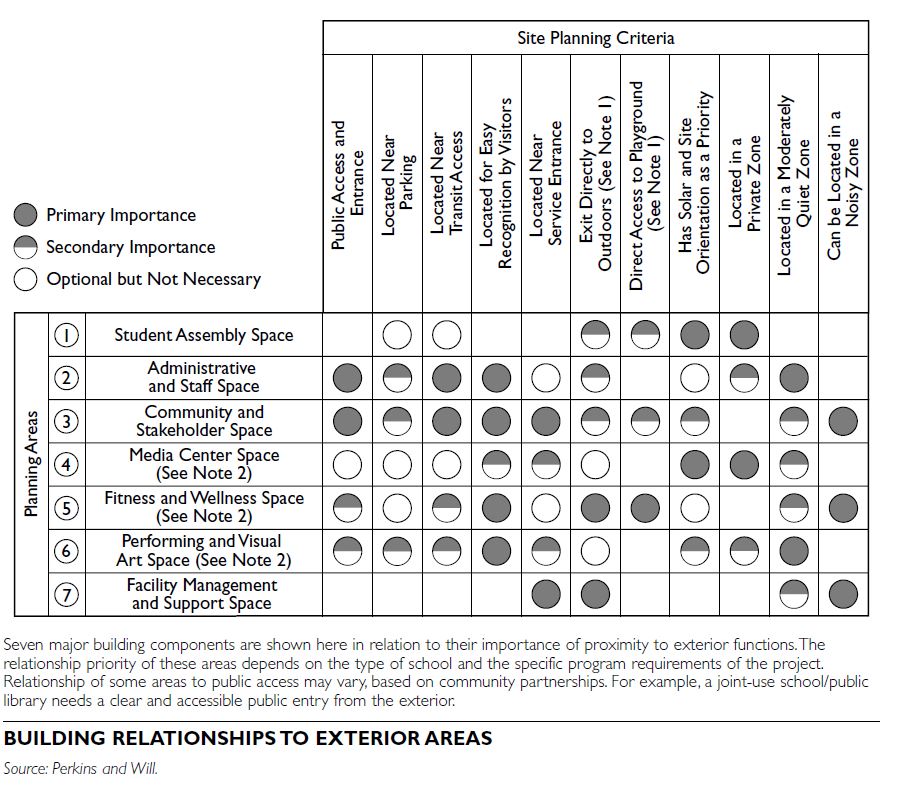
BUILDING DESIGN
The organization of building components can be divided into the following seven generalized space categories:
By cataloging space this way, exploration of design solutions for specific and distinct program areas of the facility can occur. It also provides an organized system of “parts” with which to organize the plan of the building, ensuring the proper relationships among program elements and maximizing the use of shared facilities. Determining what is the most important of these components may vary based on the age of the students being served, curriculum or district needs, the opportunities presented by the selected site, and other site selection factors mentioned earlier. In some cases there are state-mandated space standards, although these are often out of date and require more land than is necessary. Check with the state educational facilities entity to determine what is required.
Multistory solutions with more standardized and flexible space are common practice for schools in higher-density areas. These buildings are designed to change over time to meet the dynamic nature of the district or neighborhood the school serves. Proper organization of the components will maximize the use and efficiency of the building.
SITE DESIGN
Playgrounds, covered porches, and hard surface exterior spaces are all widely used at elementary schools. In locating the playground on the site, it is important to understand the curriculum and how the exterior facilities can support learning. Consider locations with the following characteristics:
When planning a “tight” school site, the building can define the site boundary or edge. Some additional design considerations for such sites include the following:
Larger sites may require additional parking and circulation guidelines relating to play fields and vehicular use. These include providing separate areas for the following:
SECURITY AND SAFETY
Building Safety
Follow these guidelines when planning building security features:
Plan spatial relationships for natural transitions from one location to another.
Locate restrooms in close proximity to classrooms.
Site Safety
Expanded hours of use, community use, and nontraditional schedules may require increased security attention. A clear set of use guidelines should be established for each project. Review Crime Prevention Through Environmental Design (CPTED) principles prior to beginning site design or when undertaking site plan review. In general, key site planning strategies include the following:
LANDSCAPE PLANTING AND LIGHTING
Landscape planting enhances the learning experience by providing environmental study opportunities and improved aesthetics. Follow these guidelines to help to provide such amenities while addressing security- related site concerns.
ENVIRONMENTAL AND SUSTAINABILITY ISSUES
In some situations, school facilities can be constructed on previously developed property, also known as brownfield sites. This decision can be controversial and should be done only after a long period of community engagement to address community concerns about environmental issues.
Environmentally sensitive design is a factor in responsible citizenship and can provide excellent learning opportunities. Environmental learning can be enhanced by site amenities that integrate the experience of those using the site. These could include the following:
In general the following guidelines related to site design should be explored thoroughly:
The U.S. Green Building Council’s LEED Green Building Rating System provides guidelines on environmentally sensitive development.
TYPES OF FACILITIES
There are four general categories of medical facilities: general hospitals, specialty care facilities, ambulatory care, and senior living facilities. When sited together, they are often configured in a medical campus setting.
General Hospitals
General hospitals provide care to the sick or injured. The care is not specific to one illness or patient type.
Specialty Care Facilities
Speciality care facilities provide care for a single or restricted patient cohort. There are three types:
Rehabilitation. Provide long-term recovery of severely physically debilitated patients.
Psychiatric: Provide treatment of patients suffering from mental illness or substance addiction.
Hospice: Offer respite palliative care for terminally ill patients.
Ambulatory Care and Medical Office
Ambulatory care and medical offices can range from typical office buildings for doctors to special treatment or diagnostic facilities.
Senior Living Facilities
Senior living facilities provide medical care or assistance to the elderly for daily living. There are four primary types of senior living facilities:
Skilled nursing facilities Provide skilled nursing care in a long-term setting.
Assisted living. These residential facilities provide assistance with daily activities for the elderly.
Independent living. These residential facilities in multifamily configurations provide varying levels of services, often including meals. When skilled nursing, assisted living, and independent living units are grouped into a single complex, they form a continuing care retirement community (CCRC).
Alzheimer’s and related dementia care. Provide continuous care and management of patients suffering from Alzheimer’s or related dementia.
Medical Campus
A medical campus contains one or more of the facilities described above, arranged in a campus configuration, with multiple buildings and pedestrian and vehicular entries.
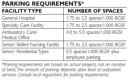
PARKING REQUIREMENTS
The parking requirements for these facilities are generally based on building gross square footage (BGSF). Residential senior living facilities have low parking needs; special senior zoning overlays typically call for half the total number of spaces required for other multifamily uses. Upscale independent living communities sometimes offer covered parking or garages. Local parking requirements may not take into account the facility’s proximity to public transportation. Developers might be able to negotiate lower requirements if proof can be offered of accessibility through other means.
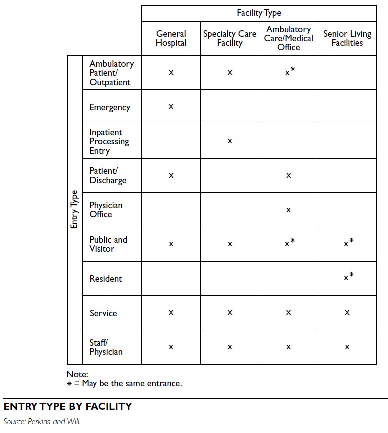
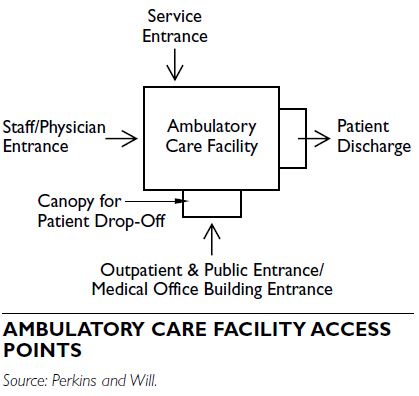
SITE CIRCULATION AND BUILDING ENTRY
On-campus circulation should be self-contained and not rely on adjacent public roadways. Separate the public (nonsecured) zones and private (secured) zones. When applicable, locate patient intake and outdoor recreational areas in the private zone. Provide appropriate access for emergency and firefighting vehicles as required by local building and safety codes.
Ambulatory Patient/Outpatient Entrance
This entrance serves patients coming and leaving in the same day and so should be adequate and convenient. It may be combined with the public and visitor’s entrance, unless privacy is a concern.
Emergency
This entrance offers direct access to the emergency department for both ambulatory and ambulance patients, which, ideally, will be provided with separate doors. The emergency entrances should be easily visible when entering the campus, and a direct, unencumbered vehicular route is required. If possible, avoid designing for left-hand turns within the campus.
Inpatient Processing Entry
The inpatient area is where patients may receive various diagnostic, treatment, or evaluation services prior to admission. The entrance to this area should accommodate special patient transport vehicles and security concerns. A vehicle sallyport may be included.
Patient Discharge
An area for discharging patients after treatment should be provided. Privacy and separation from main public areas are important, and accommodation for the disabled is required.
Physician Offices
Direct access to physician offices should be provided when an integrated building configuration is used. Public and Visitor’s Entrance
The entrance for the public and visitors should be easy to find and convenient to the public parking area, with disabled persons accommodation.
Resident
Independent senior living facilities may require a separate resident entrance.
Service
The service entrance is located away from public and patient entrances. It provides access for material delivery and a pick-up point for trash and other materials leaving the facility. It must be accessible for a variety of vehicle types, depending on facility needs.
Staff/Physician
The staff/physician entrance is separated from public areas and convenient to staff parking to ensure privacy and security.
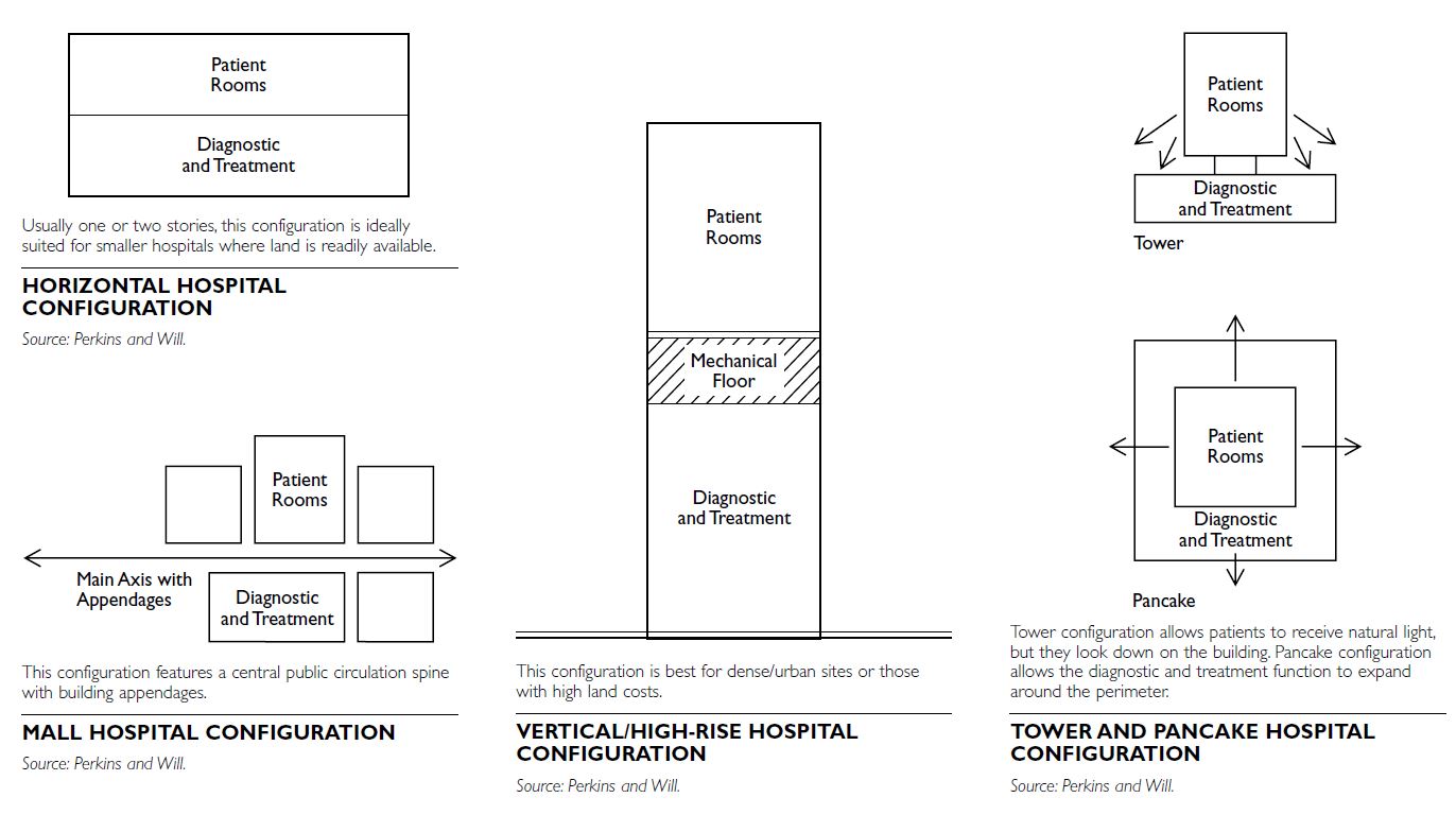
GENERAL HOSPITALS
There are four basic building configurations for general hospitals:
 Facility Growth Considerations
Hospitals change and grow throughout their existence, thus sites and buildings should be configured to allow for incremental growth without disrupting major public entrances, operations, or primary circulation paths.
Security
Buildings should be planned to allow only one or two points of entry after hours. Combining all public entrances into one location, except the emergency department, is an effective way to control access into the building even during core operating hours.
Amenities
Access to green space, water, and nature plays a critical role in the healing process. Hospitals should be carefully planned so that patients have views and access to gardens and green spaces for therapeutic purposes. In dense urban environments, roof gardens, water fountains, and other creative methods can be employed to provide positive distractions.
Campus Considerations
Most general hospitals are located on medical campuses, which, in addition to the hospital, comprise some combination of each type of facility defined in this section. The general hospital will almost always be the primary driver of the campus development and planning, but it must relate to the other facilities. Other facilities should be located close enough to the hospital to foster convenient passage between the two, but not so close that future growth of any facility is hampered by proximity of other buildings. The general hospital usually assumes a central location in a medical campus, although this is not true in all cases.
In planning new medical campuses, significant attention should be paid to potential future growth in order to ensure that sufficient property is available, that the utility infrastructure can accommodate future development, and that the locations of initial facilities do not compromise the ability of the campus to grow and change in future years. Vehicular circulation must be arranged so that access to emergency facilities is clear and direct for both ambulances and individuals.
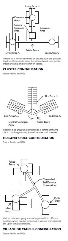
SPECIALTY CARE FACILITIES
There are three basic building configurations for specialty care facilities:
Facility Growth Considerations
Growth may occur incrementally or through major building programs.
Incremental growth. Plan “soft” areas adjacent to key programs and services. Over time, these areas are absorbed to accommodate key program growth.
Open-ended designs. Accommodate building additions easily.
The site should have sufficient space to allow for additions and related increased parking.
Campus Considerations
If a psychiatric or rehabilitative facility is located in a campus environment with other types of medical facilities, the overall campus zoning should consider the specific needs of the patient populations. It should be located in a relatively quiet zone and away from primary vehicular and pedestrian circulation paths. Access to secure outdoor areas for patients is also important.
Security
Security is a major concern for patients and staff. Psychiatric patients may pose a threat to themselves as well as staff and visitors; rehabilitative patients, due to cognitive impairments, may pose a threat to them- selves. Building designs must be scrutinized to ensure that staff observation is possible in all areas where patients are present.
Amenities
Patients may have lengths of stay that may span weeks or months. Therefore, access to gardens, protected outdoor plazas, informal social gathering areas, and educational resource areas is important to the overall treatment regimen. Staff requires lounges and outdoor areas, as well, for their own respite while on duty.
AMBULATORY CARE AND MEDICAL OFFICE FACILITIES
There are three basic building configurations for ambulatory care and medical office facilities:
Medical office buildings are generally freestanding or integrated with ambulatory care facilities.
 Facility Growth Considerations
Consolidation of multiple outpatient services offers critical mass for an ambulatory care facility by increasing patient activity at the planned facility. Generally a site is selected to maximize patient convenience and access. Outpatient surgery and outpatient diagnostic imaging areas will need to be planned with clearly identified expansion zones. Adequate acreage should be acquired to accommodate anticipated future expansion and the associated increased parking demand.
Campus Considerations
The relationship of the services provided in the medical office or ambulatory building to other on-campus medical facility buildings is important when they are all on the same campus. Physician and patient convenience must be balanced from the perspective of campus entry, connectivity to any acute care facility, and parking. Physician tenants value visibility of the buildings from public streets and convenience of entry for their patients. Patients value convenient parking and proximity to other buildings they may be required to enter during a single visit. In a campus configuration, some modification of parking requirements for a single building is sometimes appropriate,but parking should be generally considered in the broader context of the aggregate need of the campus to avoid parking overcapacity.
Security
Ingress and egress for patient, public, and medical office building entrances should be monitored. In addition to interior and building-related security controls, security cameras for the parking areas and building entrances may be used.
Amenities
Ease of access and patient convenience are essential, beginning with site selection. Dedicated physician parking is necessary when the ambulatory care facility is remote from the physicians’ primary place of business. Planning for extended-stay surgical patients who remain beyond business hours will be necessary. In medical office buildings, the parking-to-entry distance should be minimized. In integrated configurations, there should be direct access between the medical office building and the ambulatory care facility.
SENIOR LIVING FACILITIES
Basic Building Configurations
Small buildings are often organized as single-story radial wings extending from a central support/staff work core. Larger congregate care residential communities (CCRCs) may be mid- or high-rise buildings but are best planned to minimize walking distances for residents traveling from their individual rooms to community spaces, such as the dining room. Alzheimer’s and related dementia care (ARD) units are laid out to ensure that visual supervision of the residents is possible from staff areas.
Facility Growth Considerations
Senior living facilities typically change over time by expanding square footage and the range of services offered to suit the advancing age of residents; that is, independent living often becomes de facto assisted living. Construction and occupancy types should be carefully chosen to facilitate future conversion, especially if the project may change from residential care to healthcare.
Campus Considerations
Multiple subtypes of senior living facilities are frequently arranged in campus configurations, known as CCRCs. CCRCs typically contain independent living units or apartments, assisted living facilities, and skilled nursing facilities. More specialized facilities such as adult day care, Alzheimer’s care, and rehab and wellness facilities are commonly located on a medical campus focusing on senior care. When different subtypes are combined on a campus, it is important to collocate as many support functions as possible, while maintaining separate identities for each component.
Facilities and vehicular circulation should be designed to encourage residents to use the outdoor campus space. Residents who drive their own auto- mobiles need to have parking located close to entrances.
Security
Controlling building entry is both important and difficult in residential facilities because individual living units often have doors opening directly to the exterior.
Security is particularly crucial for Alzheimer and related dementia (ARD) facilities, which should be designed with safe exterior gardens surrounded by enclosures, and made accessible to residents on a 24- hour basis. Ideally, the gardens are part of wandering loops that continue through the buildings to provide therapeutic activity for active victims of dementia. Access to ARD units for families and the public must be carefully controlled to protect residents.
Amenities
CCRCs often have a variety of shared resident spaces grouped into a commons and located near the plan core
Features in common spaces and inside individual rooms that emphasize the buildings’ residential aspect, contribute to resident independence, and encourage family participation are most successful.
SIDEWALKS
The ADA Accessibility Guidelines for Buildings and Facilities (ADAAG) is the national standard for pedestrian access and travel.
ADAAG provides the minimum standards for all public and private facilities.
The American Association of State Highway and Transportation Officials (AASHTO) also provides guidelines for public rights-of-way. A Policy on Geometric Design of Highways and Streets, commonly referred to as the AASHTO Green Book, focuses primarily on vehicle use, whereas ADAAG emphasizes accessible design for pedestrians. Other organizations, such as the Institute of Transportation Engineers and the Federal Highway Administration, have also developed sidewalk and curb ramp design recommendations.
The information here is from Designing Sidewalks and Trails for Access, Part I of II: Review of Existing Guidelines and Practices (Federal Highway Administration 1999).
SIDEWALK DESIGN CHARACTERISTICS
Sidewalk design is characterized by the elements that affect usability and accessibility:
Grade
Grade is defined as the slope parallel to the direction of travel. It is calculated by dividing the vertical change in elevation by the horizontal distance covered. Running grade is the average grade along a contiguous grade. The AASHTO Green Book recommends the running grade of sidewalks be consistent with the running grade of adjacent roadways.
Maximum grade is a limited section of path that exceeds the typical running grade. In the pedestrian environment, maximum grade should be measured over 24-inch intervals, which represent the approximate length of a wheelchair wheelbase or a single walking pace. When measuring sidewalk grade, both running grade and maximum grade should be determined so that small steep sections may be detected. The rate of change of grade is the change in grade over a given distance. It is determined by measuring the grade and the distance over which it occurs for each segment of the overall distance. Rate of change of grade is measured over 24-inch (61-centimeter) intervals.
Cross-Slope
Cross-slope is the slope measured perpendicular to the direction of travel. Unlike grade, cross-slope can be measured only at specific points. Cross-slope is deter- mined by taking measurements at intervals throughout a section of sidewalk and then averaging the values.
Running cross-slope is the average cross-slope of a contiguous section of sidewalk. Often within a typical running cross-slope there are inaccessible maximum cross-slopes that exceed the running cross- slope. The distance over which a maximum cross-slope occurs significantly influences how difficult a section of sidewalk is to negotiate. Rate of change of cross-slope is the change in cross-slope over a given distance. It can be measured by placing a digital level a specified distance before and after a maximum cross-slope. The specified distance should be about 24 inches (61 centimeters) to represent the approximate stride of a pedestrian or the wheelbase of a wheelchair.
Most sidewalks are built with some degree of cross-slope to prevent water from collecting on the path by allowing water to drain into the street. Water puddles pose a slipping hazard to sidewalk users and are even more difficult to negotiate when frozen. Width Sidewalk widths affect pedestrian usability and deter- mine the types of access and other pedestrian elements that can be installed. For example, a 5-foot- (1.5-meter)-wide sidewalk is probably wide enough to accommodate pedestrian traffic in a residential area, but a much wider sidewalk would be necessary to include amenities, such as street furniture or newspaper stands. The specifications for a sidewalk’s width is called its design width. Design width extends from the curb or planting strip to any buildings or plantings that form the opposite borders of the sidewalk.
The minimum clearance width is the narrowest point on a sidewalk. If the clearance width is reduced by obstacles, such as utility poles, protruding into the sidewalk, the design width is reduced. A reduction in the design width could also create a minimum clearance width. Although most guidelines require sidewalk design widths to be at least 5 feet (1.5 meters) wide, larger design widths can accommodate more pedestrians and improve ease of access.
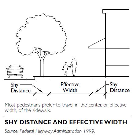
The width of the sidewalk is also affected by pedestrian travel tendencies. Pedestrians tend to travel in the center of sidewalks to separate themselves from the rush of traffic, avoid street furniture, vertical obstructions, and other pedestrians entering and exiting buildings. Pedestrians avoid the edge of the sidewalk close to the street because it often contains utility poles, bus shelters, parking meters, sign poles, and other street furniture. Pedestrians also avoid traveling in the 24 inches (61 centimeters) of the sidewalk closest to buildings because of such obstacles as retaining walls, street furniture, and fences. The sidewalk area pedestrians tend to avoid is referred to as the “shy distance.” Taking into account the shy distance, only the center 6 feet (1.83 meters) of a 10-foot (3.05-meter) sidewalk is used by pedestrians for travel. This space is called the “effective width.”
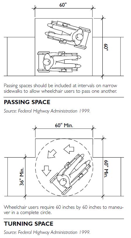
Passing Space
Passing space is a section of path wide enough to allow two wheelchair users to pass one another or travel abreast. The passing space provided should also be designed to allow one wheelchair user to turn in a complete circle. The passing space interval is the distance between passing spaces. Passing spaces should be provided when the sidewalk width is narrow for a prolonged extent because of a narrow design width or continuous obstacles. ADAAG specifies that accessible routes with fewer than 5 feet (1.5 meters) of clear width must provide passing spaces at least 5 feet (1.5 meters) wide at reasonable intervals not exceeding 200 feet (61 meters). If turning or maneuvering is necessary, a turning space of 5 square feet (0.47 square meters) should be provided.
Vertical Clearance
Vertical clearance is the minimum unobstructed vertical passage space required along a sidewalk. Obstacles such as building overhangs, tree branches, signs, and awnings often limit vertical clearance. ADAAG states that circulation spaces, such as corridors, should have at least 80 inches (203 centimeters) of headroom. ADAAG further specifies that if the vertical clearance of an area next to a circulation route is less than 80 inches (203 centimeters), a barrier must be constructed to visually disabled or blind people about the elements projecting into the circulation space.
Changes in Level
Changes in level are defined as vertical height transitions between adjacent surfaces or along the surface of a path. In the sidewalk environment, curbs with- out curb ramps, cracks, and dislocations in the surface material are common examples of changes in level. Changes in level can also occur at expansion joints between elements, such as curb ramps and gutters. The following conditions cause changes in level:
Changes in level can cause ambulatory pedestrians to trip or can catch the casters of a manual wheel- chair, causing the chair to come to an abrupt stop. People who are blind or who have poor vision might not anticipate changes in level..
Grates and Gaps
A grate is a framework of latticed or parallel bars that prevents large objects from falling through a drainage inlet but still allows water and some debris to fall through the slots. A gap is a single channel embedded in the travel surface of a path. Gaps are often found at intersections where railroad tracks are embedded into the road surface. ADAAG specifies that grates located in walking surfaces should have spaces no greater than 0.5 inches (1.27 centimeters) wide in one direction. It also states that gratings with elongated openings should be oriented so that the long dimension is perpendicular to the dominant direction of travel.
Obstacles and Protruding Objects
Obstacles in the pedestrian environment are objects that limit the vertical passage space, protrude into the circulation route, or reduce the clearance width of the sidewalk. The full width of the circulation path should be free of protruding objects. Obstacles that reduce the minimum clearance width can create significant barriers for wheelchair or walker users.
The following objects can make a sidewalk difficult for some users to traverse if they protrude into the path- way or reduce the vertical or horizontal clear space:
Surface
The surface is the material on which a person walks or wheels in the pedestrian environment. The type of surface often determines how difficult an area is to negotiate. For example, most people can traverse wood floors without much difficulty, while a gravel surface can be impossible for some people, especially wheelchair users, to cross. Surfaces in sidewalk environments are generally concrete or asphalt but commonly include tile, stone, and brick.
Firm and stable surfaces resist deformation, especially by indentation or the movement of objects. For example, a firm and stable surface, such as concrete, resists indentation from the forces applied by a walking person’s feet and reduces the rolling resistance experienced by a wheelchair. When a pedestrian or wheelchair user crosses a surface that is not firm or stable, energy that would otherwise cause forward motion deforms or displaces the surface instead. A slip-resistant surface provides enough frictional counterforce to the forces exerted in ambulation to permit effective travel. For example, a slip-resistant surface prevents a person’s shoes, crutch tips, or tires from sliding across the surface while bearing weight. A broom finish is used on many concrete sidewalks to provide sufficient slip resistance for pedestrians.
SIDEWALK ELEMENTS
Curb Ramps
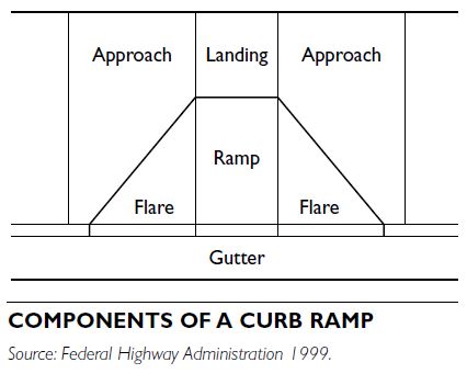
Curb ramps are most commonly found at intersections, but they may also be used at midblock crossings and medians. Curb ramps should be designed to minimize the grade, cross-slope, and changes in level experienced by users. Although there are a variety of curb ramp designs, each type of curb ramp comprises some or all of the following elements:
Landing. Level area of sidewalk at the top of a curb ramp facing the ramp path.
Approach. Section of the accessible route flank- ing the landing of a curb ramp. The approach may be slightly graded if the landing level is below the elevation of the adjoining sidewalk.
Flare. Sloped transition between the curb ramp and the sidewalk. The path along the flare has a significant cross-slope and is not considered an accessible path of travel. When the sidewalk is set back from the street, returned curbs often replace flares.
Ramp. Sloped transition between the street and the sidewalk where the grade is constant and the cross-slope is at a minimum (preferably less than 2 percent).
Gutter. Trough or dip used for drainage purposes that runs along the edge of the street and the curb or curb ramp.
Curb ramp widths should depend on the volume of pedestrian traffic at the specified intersection. The AASHTO Green Book states that curb ramps that are a minimum of 39 inches wide or of the same width as the approach sidewalk should be provided at cross- walks. Although ramp widths are permitted to vary, they must always be wide enough for comfortable use by wheelchair users. Curb ramps provide critical access between the sidewalk and the street for people with mobility impairments. ADAAG specifies that curb ramps should be at least 3 feet (0.91 meters) wide, not including the width of the flared sides.
Gutters
The slopes of adjacent gutters and streets significantly affect the overall accessibility of curb ramps. Any amount of height transition between the curb ramp and the gutter can compound the difficulties caused by rapidly changing grades. According to ADAAG, the slope of the road or gutter surface immediately adjacent to the curb ramp should not exceed 5 percent, and the transition between the ramp and the gutter should be smooth.
Landings
Landings allow people with mobility impairments to move completely off the curb ramp and onto the sidewalk. Curb ramps without landings force wheel- chair users entering the ramp from the street, as well as people turning the corner, to travel on the ramp flares. According to ADAAG, the landing should be a level surface at least 3 feet (0.91 meters) wide to prevent pedestrians from having to cross the curb ramp flare. ADAAG recommends a 4-foot (1.22-meter) landing for perpendicular curb ramps and a 5-foot (1.5-meter) landing for parallel curb ramps.
Flares
The flared sides of curb ramps provide a graded transition between the ramp and the surrounding sidewalk. Flares are not considered an accessible path of travel because they are generally steeper than the ramp and often feature significant cross-slopes with excessive rate of change of cross-slope. Flares may be replaced with returned curbs if the curb ramp is located where a pedestrian does not have to walk across the ramp or if guardrails or handrails protect the sides.
CURB RAMP TYPES
Curb ramps can be configured in a variety of patterns, depending on the location, type of street, and existing design constraints. Curb ramps are often categorized by their position relative to the curb line. Many sidewalk characteristics, including width, elevation of buildings, and position of street furniture, can affect the curb ramp design chosen. The four most common configurations are perpendicular, parallel, diagonal, and built-up ramps.
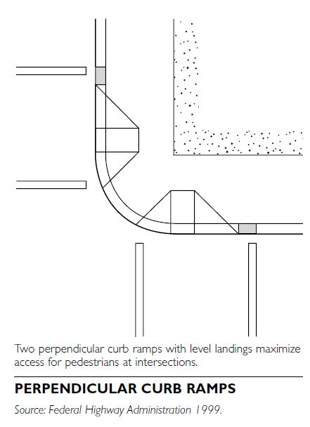
Perpendicular Curb Ramps
Perpendicular curb ramps are often installed in pairs at a corner. For new construction, two perpendicular curb ramps with level landings should be provided at street crossings. The path of travel along a perpendicular curb ramp is oriented at a 90-degree angle to the curb face. When the sidewalk is narrow, it can be costly to purchase additional right-of-way necessary to accommodate a landing for perpendicular curb ramps. An alternative to purchasing more land is to extend the corner into the parking lane with a curb extension, also known as a “bulbout.”
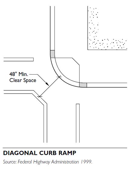
Diagonal Curb Ramps
Diagonal curb ramps are single curb ramps installed at the apex of a corner. They force pedestrians descending the ramp to proceed into the intersection before turning to the left or right to cross the street. This puts them in danger of being hit by turning cars. A marked clear space of 4 feet (1.22 meters) at the base of diagonal curb ramps is necessary to allow ramp users in wheelchairs enough room to maneuver into the crosswalk.
In many situations, diagonal curb ramps are less costly to install than two perpendicular curb ramps. While these ramps might save money, they create potential safety and mobility problems for pedestrians, including reduced maneuverability and increased interaction with turning vehicles, particularly in areas with high traffic volumes. Diagonal curb ramps are not desirable in new construction, but might be effective when retrofitting is being done and there is not enough space for two accessible perpendicular curb ramps.
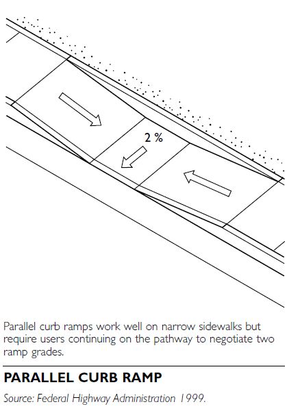
Parallel Curb Ramps
The path of travel along a parallel curb ramp is a continuation of the sidewalk, as parallel curb ramps provide an accessible transition to the street on narrow sidewalks. If the landing on parallel curb ramps is not sloped toward the gutter (no more than 2 per- cent), however, water and debris can pool there and obstruct passage along the sidewalk.
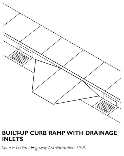
Built-up Curb Ramps
Built-up curb ramps are oriented in the same direction as perpendicular curb ramps but project out from the curb. For this reason, built-up curb ramps can be installed on narrow sidewalks but are most often installed in parking lots. Built-up curb ramps should not extend into a vehicular traffic lane or bicycle lanes. Built-up curb ramps have additional drainage requirements because they block the gutter. Possible solutions include providing drainage inlets or placing a drainage pipe under the curb ramp.
CROSSWALKS
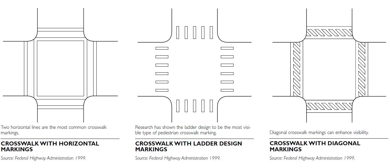
Crosswalks are a critical part of the pedestrian net- work. A crosswalk is that part of the roadway designated for the use of pedestrians in crossing the street. Crosswalks may be either marked or unmarked. Marked crosswalks are most effective when motorists can identify them easily; pedestrians, too, especially those with low vision, benefit from clearly marked crosswalks.
Most state departments of transportation follow the Manual of Uniform Traffic Control Devices (MUTCD) guidelines for marking crosswalks. Although the MUTCD does permit some variations for additional visibility, the basic specifications call for solid white lines not less than 6 inches (15.24 centimeters) mark- ing both edges of the crosswalk and spaced at least 72 inches (183 centimeters) apart.
Crossing Times
An individual’s starting pace and walking pace vary depending on their personal situation. Older pedestrians might require longer starting times to verify that cars have stopped. They also might have slower reaction times and walking speeds. Powered wheelchair
users and manual wheelchair users on level or down- hill slopes might travel faster than other pedestrians; but on uphill slopes, manual wheelchair users might have slower travel speeds. At intersections without audible pedestrian signals, people with visual impairments generally require longer starting times because they rely on the sound of traffic for signal-timing information.
The AASHTO Green Book suggests an average walking speed in the range of 3.3 feet/second (1 meter/second) to 5.9 feet/second (1.8 meters/second), whereas the MUTCD assumes an average walking speed of 4 feet/second (1.22 meters/second). For older pedestrians, the AASHTO Green Book suggests a walking rate of 3.28 feet/second (approximately 1 meter/second). However, research on pedestrian walking speeds has demonstrated that more than 60 percent of pedestrians walk more slowly than the speeds suggested by both the AASHTO Green Book and the MUTCD. In fact, 15 per- cent of pedestrians walk at less than 3.5 feet/second (1.07 meters/second).
Pedestrians of all mobility levels need to cross intersections, and when crossing times accommodate only those who walk at or above the average walking speed, intersections become unusable for people who walk at a slower pace. To accommodate the slower walking speeds of some pedestrians, transportation agencies should consider extending their pedestrian signal cycles. Signal timing should be determined on a case-by-case basis, although extended signal cycles are strongly recommended at busy intersections that are unusually long or difficult to negotiate.
Midblock Crossings
Midblock crossings are pedestrian crossing points not at intersections. They are often installed to provide more frequent crossing opportunities in areas with heavy pedestrian traffic. For midblock crossings to be accessible to people with mobility impairments, a curb ramp needs to be installed at both ends of the crossing along a direct line of travel. Where the curb ramps are offset, pedestrians who rely on the curb ramps are forced to travel in the street.
Midblock crossings spanning multiple lanes can be difficult for some pedestrians to negotiate. In these situations, curb extensions can be effective in reducing crossing times and increasing visibility between pedestrians and motorists. A median is another effective method to reduce crossing distances.
SIGHT DISTANCES
Sight distance is the distance one can view along an unobstructed line of sight. Adequate sight distances between pedestrians and motorists increase pedestrian safety. Motorists also need appropriate sight distances to see traffic signals. In particular, vertical sight distance can be important for drivers of high vehicles, such as SUVs, trucks, and buses, whose sight lines might be blocked by trees or signs. Although bollards, landscaping, parking, benches, or bus shelters make pedestrian areas more inviting by calming traffic and providing amenities, they can also clutter the environment and block sight lines between motorists and pedestrians waiting to cross the intersection. Trimming vegetation, relocating signs, and hanging more than one sign or traffic signal on one arm pole where permitted by the MUTCD can improve sight distances at corners. Parked cars near the intersection or midblock crossing can also reduce sight distances. Installing curb extensions physically deters parking at intersection corners and improves the visibility of pedestrians. Curb extensions can also increase the angle at which pedestrians meet motor vehicles, improving the visibility of both. In addition, curb extensions shorten crossing distances and provide sidewalk space for curb ramps with landings.
GRADE-SEPARATED CROSSINGS
Grade-separated crossings are facilities allowing pedestrians and motor vehicles to cross at different levels. Examples of grade-separated crossings include overpasses and underpasses. Overpasses might be bridges, elevated walkways, skywalks, or skyways. Underpasses are pedestrian tunnels and below-grade pedestrian networks. Some grade-separated crossings are very steep and difficult for people with mobility impairments to negotiate. In addition, grade-separated crossings are extremely costly to construct and are often not considered pedestrian-friendly because pedestrians are forced to travel out of their way to use the underpass or overpass. The effectiveness of a grade-separated crossing depends on whether pedestrians perceive it as easier to use than a street crossing.
The needs of pedestrians should be a high priority at grade-separated crossings. If designed correctly, grade-separated crossings can reduce pedestrian- vehicle conflicts and potential accidents by allowing pedestrians to avoid crossing the path of traffic. They can also limit vehicle delay, increase highway capacity, and reduce vehicle accidents when appropriately located and designed. Grade-separated crossings are most efficient in areas where pedestrian attractions such as shopping centers, large schools, recreational facilities, parking garages, and other activity centers are separated from pedestrian generators by high volume and/or high-speed arterial streets.
Well-designed grade-separated crossings minimize slopes, feel open and safe, and are well lit. Minimizing the slope of a grade-separated crossing is often difficult because a significant rise, generally from 14 to 18 feet (4.27 to 5.49 meters), must be accommodated. Underpasses might invite crime if insufficiently lit and are seldom traveled. Underpasses can also be more expensive to install than other pedestrian facilities because a tunnel must be dug and utility lines relocated. Tunnels are more inviting to use when they are brightened with skylights or artificial lighting and are wide and high enough to feel open and airy.
MEDIANS AND ISLANDS Medians and islands help pedestrians cross streets by providing refuge areas physically separated from the automobile path of travel. A median separates opposing lanes of traffic. An island is a protected spot within a crosswalk for pedestrians to wait to continue crossing the street or to board transit. Medians and islands are useful at irregularly shaped intersections, such as where two roads converge into one.
Medians and islands reduce the crossing distance from the curb and allow pedestrians to cross during smaller gaps in traffic. They are useful to pedestrians who are unable to judge distances accurately and to those who walk slowly. Because medians and islands separate traffic into channels going in specific directions, they require crossing pedestrians to watch for traffic coming in only one direction.
SIGNAGE
Objective signage provides users with information to help them make informed choices about their travel routes. Most agencies rely on the MUTCD for sign guidelines. Pedestrian signs should not be placed in locations where they obstruct the minimum clearance width or protrude into the pathway. In the sidewalk environment, signage should be supplemented with audible or tactile information so that it is accessible to people with visual impairments. Braille and raised lettering are not addressed in the MUTCD.
The majority of signs in the public right-of-way are directed at the motorist. Although these signs often affect pedestrians, they are usually not intended for or positioned to be seen by them. For example, the street name signs on many large arterials are hung in the center of the intersection, making them essentially invisible to pedestrians traveling along the sidewalk. Pedestrians might even be put in danger because important safety information, such as yield signage, is not easily visible.
Targeting more signs toward pedestrians would improve safety and permit them to identify routes requiring the least effort for travel. Warning signs similar to standard traffic warning signs would provide information on sidewalk characteristics, such as steep grades. To date, these types of signs have not been introduced to the MUTCD.
DRAINAGE
Sidewalks provide the main conduit for draining the walking surface, adjacent properties, and, in some cases, the roadway. Therefore, sidewalks and side- walk elements, such as curb ramps and driveway crossings, must be designed to provide efficient drainage as well as good access. The AASHTO Green Book, adopted by most states, provides slope ranges based on street type.
Local topography and weather conditions also affect how steeply sidewalks, gutters, and roads should be sloped to provide adequate drainage. According to the AASHTO Green Book, a cross-slope between 1.5 to 2 percent provides effective drainage on paved surfaces in most weather conditions. Gutters are generally sloped more steeply than the roadway to increase runoff velocity.
The AASHTO Green Book suggests gutters have a cross-slope ranging from 5 to 8 percent, whereas ADAAG specifies a maximum 5 percent slope. The ADAAG provision is designed to prevent wheelchair users from hitting their footrests on the ramp or gutter and potentially being thrown forward out of their wheelchairs. A wider gutter can be used to drain larger volumes of water without increasing the slope experienced by curb ramp users. However, widening the gutter might require the purchase of additional right-of-way. According to the AASHTO Green Book, gutters formed in combination with curbs should range from 12 inches (30.48 centimeters) to 71 inches (180.34 centimeters) wide.
Storm drains and catch basins are normally placed where they will intercept surface water runoff. Installing a curb ramp at a point of strategic runoff interception can compromise effective drainage. Regrading the section of road or curb ramp location to alter drainage patterns can resolve some situations in which drainage concerns conflict with accessibility requirements.
Ideally, inlets should be placed uphill of crossings or curb ramps to drain water before it can puddle where pedestrians are crossing. In locations with heavy rainfall, more frequent drainage inlets, more strategic placement of inlets, and basin pickups will also reduce the frequency of puddles.
MAINTENANCE
Sidewalks are prone to damage caused by environmental conditions. Maintaining sidewalk elements in good condition is an essential part of providing access to public rights-of-way. Sidewalks in poor repair can limit access and threaten the health and safety of pedestrians. If sidewalks are in poor condition or nonexistent, pedestrians may be forced to travel in the street. Maintenance problems are usu- ally identified by pedestrians who report the location to the municipal authorities. Identification of locations requiring maintenance may be done in conjunction with a city’s accessibility improvement program. Effective maintenance programs are quick to identify conditions that can impede access and respond with repairs.
Assessing sidewalks for accessibility should be an integral part of maintenance survey programs. Some cities survey and repair all sidewalks in regular cycles. Other cities make or enforce repairs only if a com- plaint is filed. Cities also might have pavement management programs and personnel devoted entirely to inspecting and repairing damaged access routes. Sidewalk inspectors typically look for conditions that are likely to inhibit access or cause pedestrians to injure themselves. These include: step separation, badly cracked concrete, settled areas that trap water, tree root damage, and noncompliant driveway flares.
Although sidewalks are elements of the public right-of-way, many city charters assign the owner of the adjacent property with responsibility for sidewalk upkeep. It is common for city charters to specify that the city cannot be held liable for any accident or injury due to sidewalk conditions. Homeowners are commonly allowed to decide whether to hire a con- tractor, perform repairs on their own, or have the city do the repair. The homeowners’ associations in some neighborhoods address right-of-way maintenance to minimize the cost to individual members. Some cities subsidize property owners for repairing sidewalks. Local laws also might dictate whether a homeowner must engage a professional contractor to undertake sidewalk repair. If municipal inspectors review and approve sidewalk repairs, the finished sidewalks are more likely to meet pedestrian access needs.
FUNCTIONAL CLASSIFICATION SYSTEM FOR URBAN STREETS
The functional classification system developed by the Federal Highway Administration (FHWA) in 1962 is widely used to define the traffic-carrying function of streets. For urban streets, there are four classifications:
principal arterials, minor arterials, collector streets, and local streets.
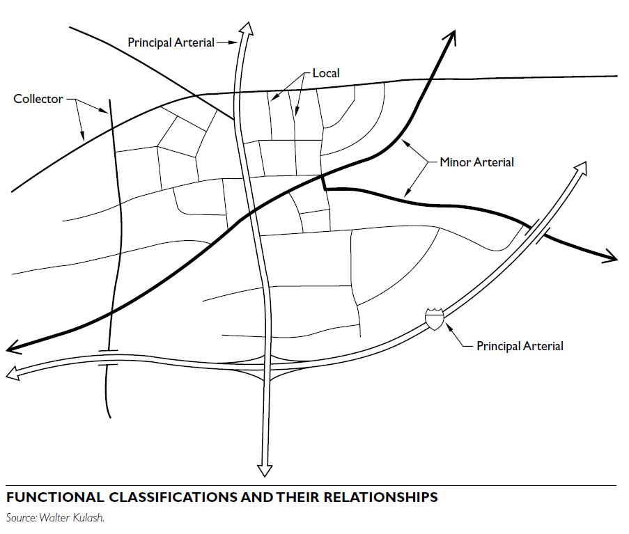
Principal Arterials
Principal arterials provide long-distance “trunk- line” continuous routes within and between urban areas. Typically, but with some important exceptions, they carry high volumes of traffic at high speeds. Freeways, including interstates, are principal arterials.
Minor Arterials
The backbone of the urban street network, minor arterials are continuous routes through urban areas. They are frequently designated as touring (i.e., U.S. or state-numbered) routes. Accounting for only 10 per- cent of street mileage, they carry more than half of all vehicle miles of travel. They may be state, county, or city streets.
Most trips include arterial streets. They contain most of a city’s commercial and institutional uses. The traffic function of minor arterial streets is challenged because of their attractiveness as business addresses, an attractiveness fostered by the traffic function of the street itself.
Collector Streets
With continuity over short segments (one-fourth to one-half mile; 0.4 to 0.8 kilometers), collector streets are minor tributaries, gathering traffic from numerous smaller (local) streets and delivering it to and from minor arterials. Seldom designated as numbered touring routes, collectors are usually city or county streets. Most collectors are bordered by properties (both business and residential) with driveways to the street.
Local Streets
Local streets include all streets not on a “higher” system. They comprise 90 percent of street mileage but carry less than 10 percent of the total vehicle miles of travel.
These streets may be short in length or frequently interrupted by traffic control devices (stop signs or signals). Travel distance on local streets is short, typically to the nearest collector street. Speeds are low (20 to 30 mph; 32.2 to 48.3 kilometers/hour). Usually, local streets are city streets, and seldom are part of a numbered touring route. Local streets often have numerous driveways, as they are the addresses for most homes, as well as many nonresidential land uses (professional office, small industrial, churches) not requiring visibility to large numbers of passing motorists.
ACCESS AND MOBILITY
All urban streets provide some mixture of mobility and access. Mobility is the movement of through traffic with neither origin nor destination in the immediate area. Access is the connection to immediately fronting properties. Arterial streets, located at the mobility end of the mobility/access spectrum, provide large amounts of service to through traffic, but little or no access to surrounding land. Local streets, located at the access end of the spectrum, provide unlimited access to adjacent properties, but little service to through travel. Collector streets are in the midrange of the spectrum. They provide property access with mobility appropriate for connecting local streets to the higher-speed arterials.
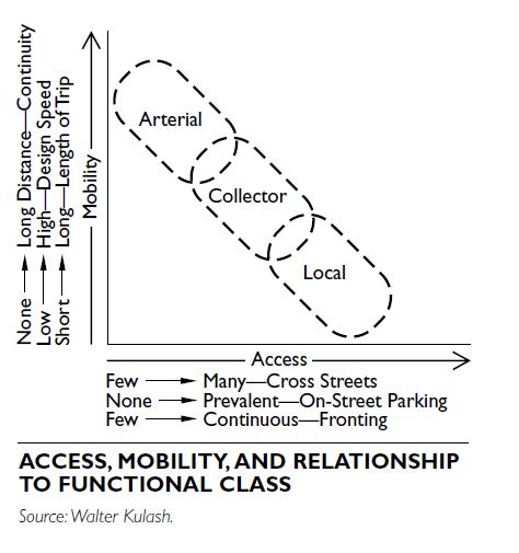
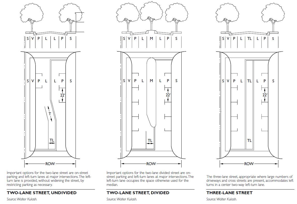
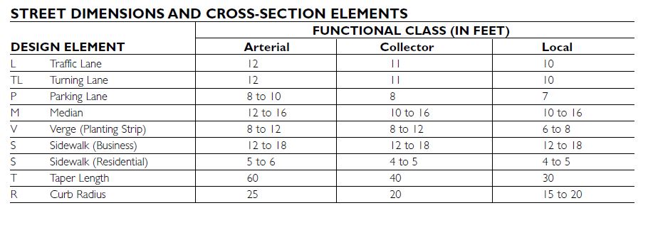
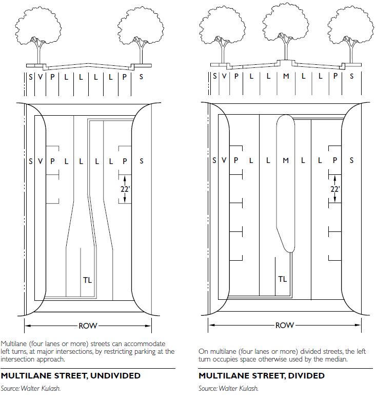
COMPONENTS OF STREET NETWORKS
With respect to their traffic function, there are four functional classifications of urban streets:
• Principal arterials • Minor arterials • Collector streets • Local streets
Further descriptions of these street types can be found in Hierarchy of Streets and Roads. The information here focuses on their relationship to each other as part of larger street systems and in terms of their connectivity.
STREET SPACING GUIDELINES
Principal arterials should be located every three to four miles (4.83 to 6.44 kilometers) in urban areas. Minor arterials should be spaced at around one-mile (1.61-kilometer) intervals from other arterials (principal or minor). Collector streets should be spaced roughly one- half mile (0.8 kilometers) from arterials. Local streets complete the network, with a block spacing appropriate to the land use—typically 300 to 500 feet (91.4 to 152.4 meters) in business districts and 250 to 600 feet (76.2 to 182.9 meters) in residential neighborhoods.
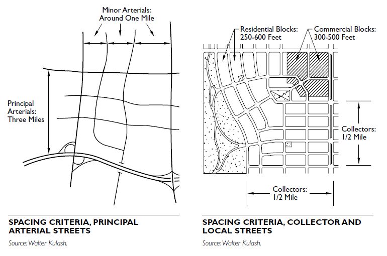
LOCAL STREET PATTERNS The functions of local streets—to provide address and immediate access—can be accomplished equally well under a wide variety of network patterns. Typical street patterns include:
• Grid • Grid and squares • Web • Radial • Curvilinear • Irregular
Regardless of pattern, the factors most important for traffic are connectivity and legibility.
STREET CONNECTIVITY
Street connectivity can be defined as the quantity and quality of connections in the street network. The pur- pose of the street network is to connect one place to another. The design of the street network determines how direct or indirect the connections are and governs the number of different paths that connect two places. A traditional rectilinear street grid provides relatively direct connections and multiple routes and thus has high connectivity. In contrast, the curvilinear networks dominated by cul-de-sacs that are more typical of modern suburban subdivisions often provide relatively indirect connections and few routes and thus have low connectivity.
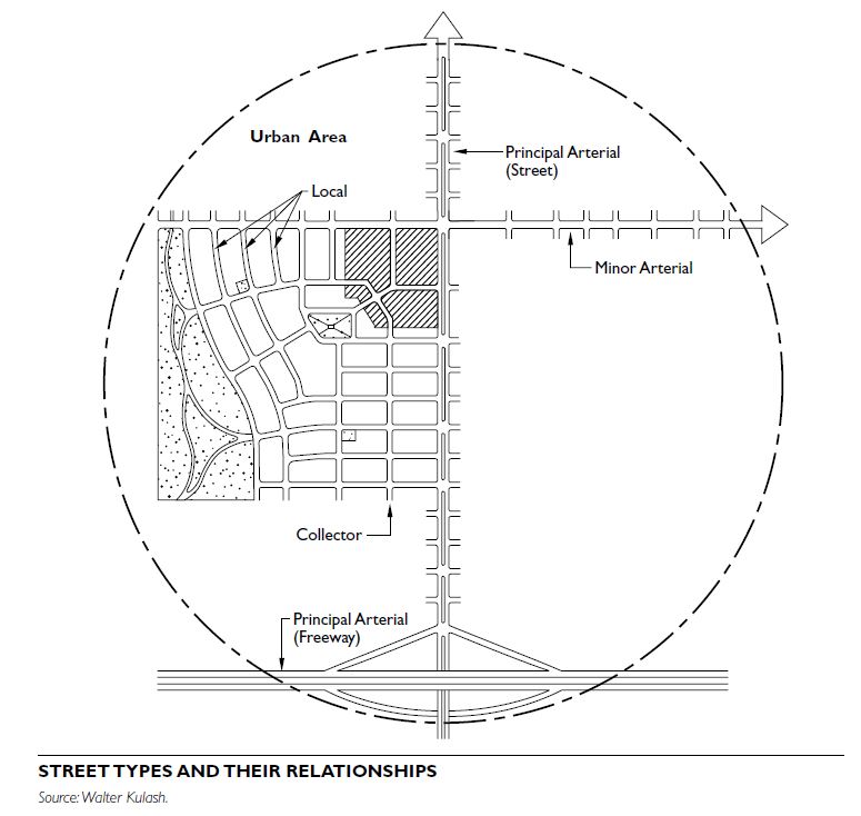
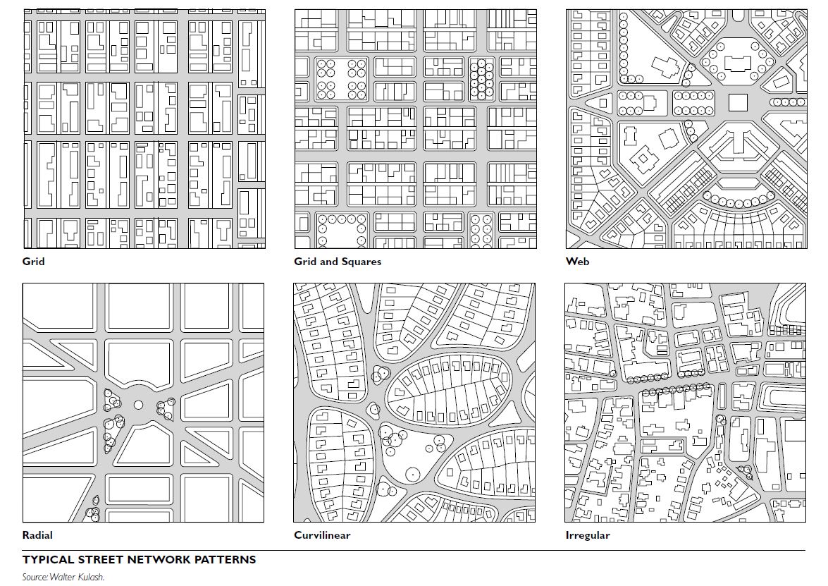
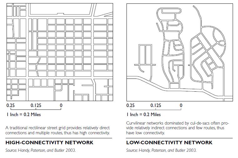
Street connectivity has important implications for travel choices and emergency access. The distance from one point to another, as determined by the directness of the route through the street network, influences the choice to travel to that destination and by what mode. Longer distances reduce the likelihood that an individual will travel to that destination or will choose to walk or bike. For that reason, planners and public health officials have expressed concern that networks with low connectivity discourage walking and biking, thereby increasing vehicle travel and reducing physical activity. Emergency service providers have also expressed concern over low-connectivity networks, which may contribute to longer response times and limit the number of routes for emergency access or evacuation.
Range of Connectivity of Local Streets
In traditional American towns, both historical and neotraditional, all local streets were connected. In a number of cities, the requirement for connectivity now focuses on connection in major compass directions, rather than on connection of all local streets. Connectivity at the collector street level can be maintained even with inward-turned residential subdivisions. The unconnected subdivision with a single access point, a major contributor to arterial street congestion, is not advisable and is now precluded by a growing number of local land development regulations.
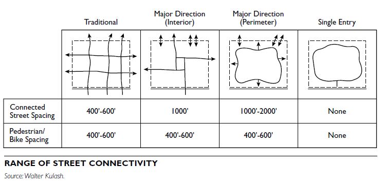
Connectivity Standards
The design of the street network is determined by standard practices and by local land development codes. Many cities specify minimum block lengths and otherwise encourage street networks that dis- courage through traffic by minimizing connectivity. However, a growing number of cities in the United States have adopted street connectivity standards that encourage greater connectivity in the street net- work (Handy et al. 2003). These cities have used one of two techniques to establish street connectivity standards: block length requirements or connectivity indexes.
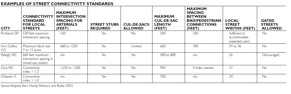
Block Length Standards
By establishing a block length standard, cities control the spacing between local streets. These requirements can take the form of a maximum allowed block length or a maximum allowed inter- section spacing. The two forms are essentially equivalent, although the exact measurements may vary depending on the widths of streets and rights- of-way. Block lengths are usually measured as the distance from curb face to curb face of intersecting streets, while intersection spacing is measured as the distance between centerlines for intersecting streets.
Maximum block length requirements typically fall into the range of 300 to 600 feet (91.4 to 182.9 meters). A variation on this approach is to restrict block size, measured as width by length, number of acres, or block perimeter. Block length standards are usually coupled with significant restrictions on cul-de-sacs, with lengths limited to 200 to 300 feet (61 to 91.4 meters) and use limited to places where street connections would be impractical.
Connectivity Index
A connectivity index is the ratio of the number of links to the number of nodes in the network.
Links are street segments, while nodes are intersections. A higher connectivity index reflects a greater number of street segments entering each intersection and thus a higher level of connectivity for the net- work. Cities have established different rules for counting nodes and links at the boundary of the area of interest. These different rules lead to slightly different values of the index for the same network. Minimum standards for connectivity indexes typically fall into the range of 1.2 to 1.4. Cities using a connectivity index usually do not restrict the use of cul-de-sacs, as long as the minimum connectivity standard is met.
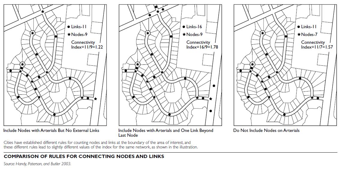
Connectivity in Practice
Street connectivity standards are often accompanied by other standards that affect the street network. Some cities have adopted connectivity standards that apply specifically to connections between residential areas and arterials. More commonly, cities incorporate requirements for street stubs and the mapping of future streets into their connectivity requirements as a way of ensuring connectivity with future streets. Most cities with connectivity standards have adopted narrower street standards to avoid a net increase in the amount of paving associated with the street network and to discourage the use of residential streets for through traffic. Cities often couple restrictions on gated communities with connectivity standards, and many cities have adopted separate standards for bicycle and pedestrian connections as well. Cities have adopted different packages of standards depending on local conditions and objectives.
VEHICLE TURNING RADII
DESIGN VEHICLES FOR URBAN STREETS
The vehicle to be accommodated—the design vehicle—is an important control in the design of urban streets. The most important characteristic of the design vehicle, its turning radius, dictates intersection design. For urban streets, four design vehicles are defined in the American Association of State Highway and Transportation Officials (AASHTO) Green Book.
Passenger Vehicle (P): Includes automobiles, vans, SUVs, and light trucks. Single-Unit Truck (SU-30): Used for most local commercial and home deliveries and municipal services. Conventional School Bus (S-BUS-36): The standard school bus. Tractor-Trailer (WB-50): In increasing use for delivery to businesses.
SELECTING THE APPROPRIATE DESIGN VEHICLE
Design vehicles are selected according to the intended traffic use or functional classification of the street. A design for a small vehicle (for example, Passenger Vehicle, “P”) does not preclude a street’s use by larger vehicles, but may require that larger vehicles encroach into other lanes or directions of traffic while making intersection-turning movements.
Vehicle Turning Radii
Important elements of turning radii are the wheel paths, which define the needed width of pavement, and the front overhang, which is the zone beyond the pavement edge that must be clear of obstructions above curb height. The turning movement templates are shown for a right turn, typically the most constricted on urban streets. For left turns, the turning template is simply the reverse of those shown.
Encroachment by Design Vehicles at Intersections
All intersections must accommodate the P template without encroachment on either the approach or departure leg. Large vehicles, operating on streets designed for smaller vehicles, can encroach into other lanes, in both the same and opposite directions of travel.
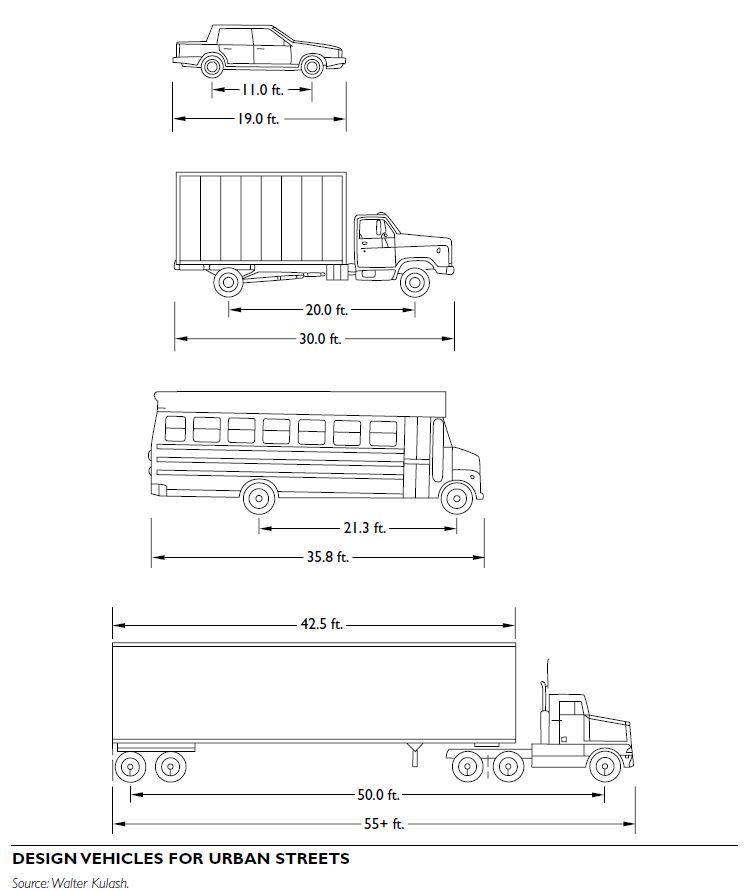
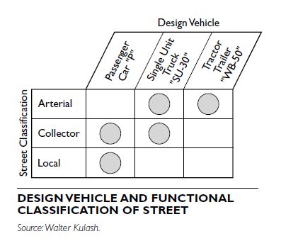
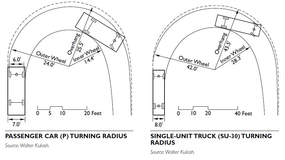
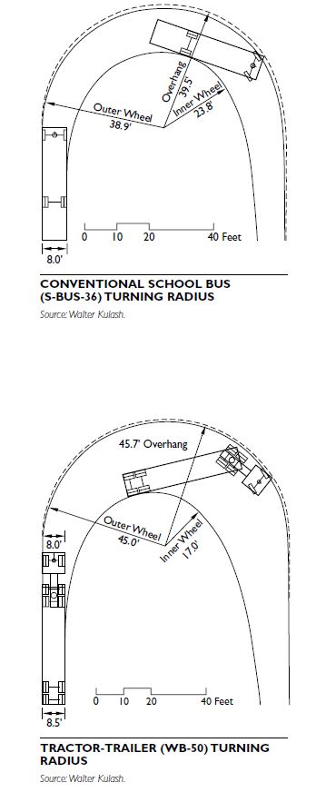
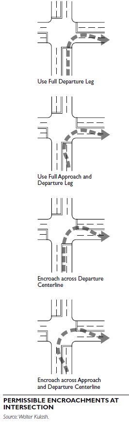
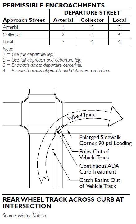
On very narrow streets, large vehicles, in particular the WB-50 vehicles, may be accommodated at inter- sections by permitting the rear wheel of the trailer to track across the sidewalk.
Additional Information
Vehicle turning radii, as established by AASHTO, are based on broad categories of vehicle types, each of which encompasses a wide variety of actual vehicles on the road. Information on passenger vehicle dimensions for parking design, provided elsewhere in this section, provides a more detailed breakdown of vehicle types within the various categories. For off-street design applications, such as parking and driveways, the more detailed versions are appropriate. For public streets, the AASHTO templates provided here are definitive.
TRAFFIC CALMING
The Institute of Transportation Engineers (ITE) defines traffic calming as the combination of mainly physical measures that reduce the negative effects of motor vehicle use, alter driver behavior, and improve conditions for nonmotorized street users (ITE Journal, July 1997). The American Planning Association describes it as a form of traffic planning that seeks to equalize the use of streets among automobiles, pedestrians, bicylists, and playing children (Hoyle 1995). However it is defined, traffic calming is part of a nationwide change in how we are building our transportation system.
Traffic calming measures have been used primarily on residential streets but are sometimes used on collectors and arterials. Communities are increasingly using center medians in roadways, along with other traffic calming measures to create boulevards and parkways as alternatives to standard arterial streets.
TRAFFIC CALMING TOOLS
A variety of devices and techniques are used to help reduce traffic speed and volume. Detailed information on engineering and aesthetic issues, legal authority and liability, emergency response, and other issues can be found in Traffic Calming: State of the Practice, published by ITE in cooperation with the Federal Highway Administration (FHWA) (Ewing 1999).
Traffic calming measures impact both vehicle speed and volume on roadways. The ITE publication classifies traffic calming measures according to their dominant effect. Combinations of various measures can dramatically affect both speed and volume when properly applied. Illustrations shown here provide examples of traffic calming devices and applications, divided into categories based on the ITE model.
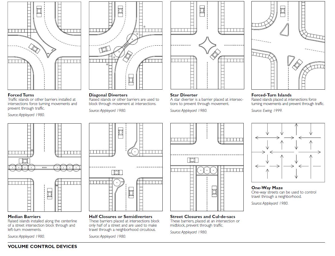
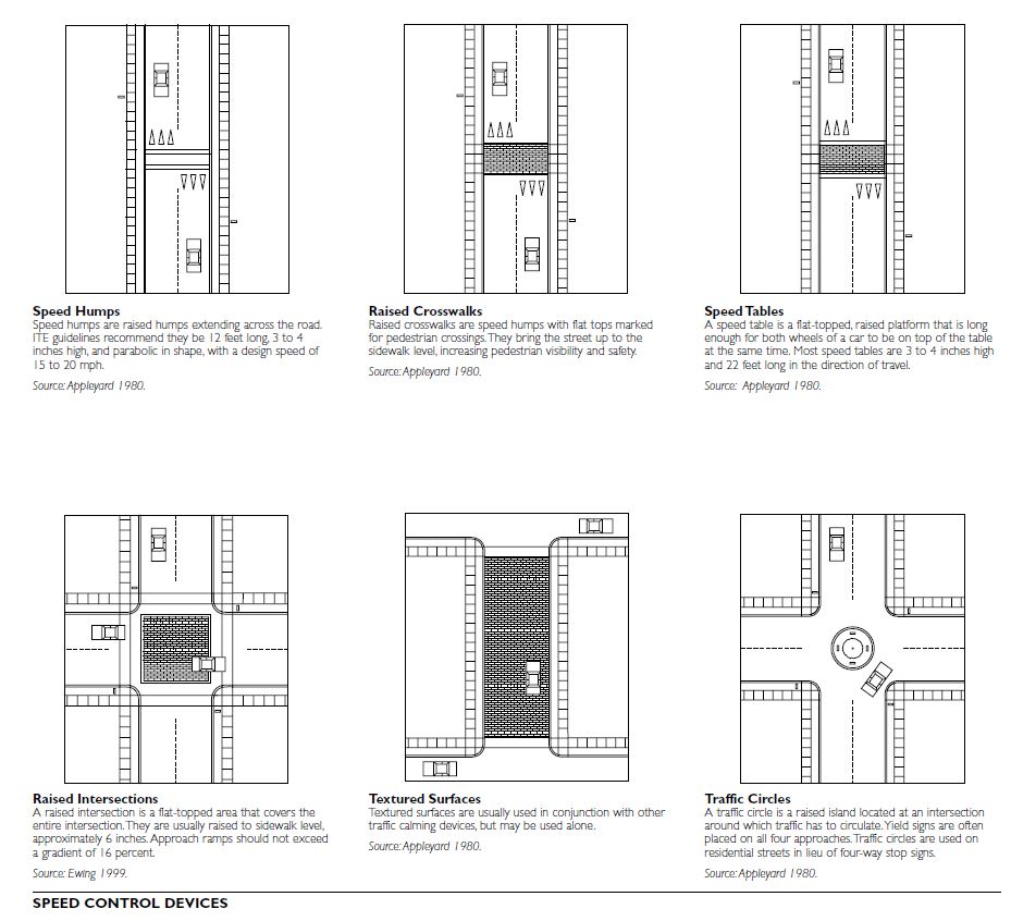
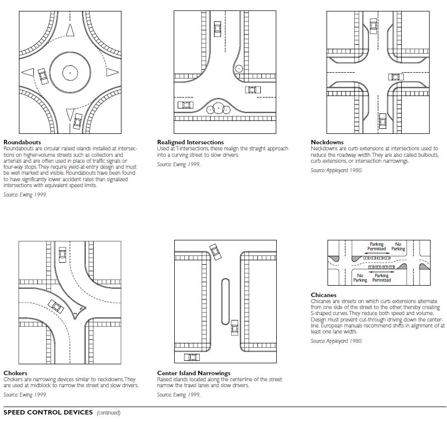
Traffic Calming Program Models
Many communities use traffic calming programs that include the “three Es”—education, enforcement, and engineering. These programs involve major campaigns to educate the public and increase enforcement in problem areas, in addition to implementing traffic calming programs.
In traffic calming programs, the most important elements are public involvement and procedures for selection of appropriate traffic calming devices. Poor public input processes can result in a failed traffic calming program.
Public Input Processes
Traffic calming programs are either in reaction to citizen requests for action or a result of staff identifying problems and initiating action. Traffic calming can be applied to only one problem area, or it may involve study and implementation of an areawide program. Some communities have used warrants for traffic calming programs. Warrants are minimum requirements that should be met before a device is installed. Warrants are used in most communities for installation of traffic signals and stop signs (Ewing 1999).
In most communities, local officials have found that, for a traffic calming program to achieve success, a majority of the local residents must be in favor of it. Many communities require that 60 to 70 percent of the affected property owners agree to the proposed program through a petition signature or vote. Neighborhood workshops and charrettes are two techniques that can be used to gain community input and support. The basic steps in most traffic calming programs are to:
PEDESTRIAN-FRIENDLY STREETS
Pedestrian-friendly streets are designed to be more accommodating to pedestrian traffic than are conventionally designed streets. Pedestrian traffic here includes bicyclists, the physically handicapped, transit users, and those of all ages on foot. Pedestrian-friendly streets include yield or queuing streets along with narrower vehicular traffic lanes. Yield streets require that one vehicle yield to another as they pass. Parking density works in part to control that type of movement.
Pedestrian-friendly streets are becoming a popular design strategy for creating walkable neighborhoods, new or retrofitted. This trend is associated with smart growth, context-sensitive design, new urbanism, and other current land development approaches.
Efforts to calm traffic in walkable environments through street design have demonstrated a reduction in accident severity, accident frequency, and environmental impact. Both pedestrian and vehicular accident severity is reduced when vehicles are traveling at slower speeds. When designed properly, narrower streets have design speeds either equal to or less than 20 miles per hour. The Abbreviated Injury Scale (AIS) indicates that when vehicles travel above 20 miles an hour, the potential for serious injury increases greatly.
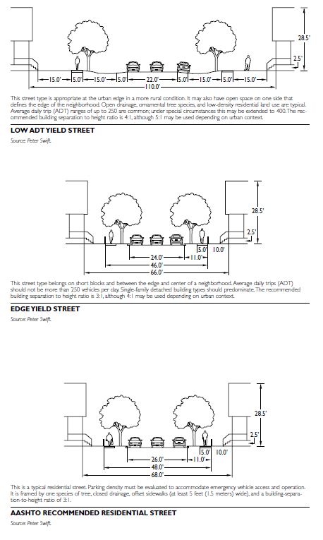
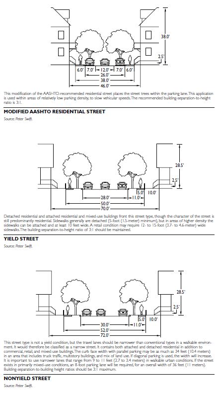
SCALE AND CONTEXT
Context is the single most important variable in determining the suitable width for a pedestrian-friendly street. The dimensions of the street will vary depending on several factors, including but not limited to:
The street should have parking allowed on both sides as a minimum in all circumstances. This helps reduce speeds, keeps the driver alert, and accommodates activity between the public and private realm.
Context is also relevant to federal, state, and local authorities for both infill and new development projects in urban areas. Federal funding mechanisms for thoroughfare projects require certain criteria be met for the project to qualify, such as the funding of street improvements for redevelopment or new development along state highways. A number of design techniques at the federal level recognize the importance of narrower lanes, wider sidewalks, and transit and access design criteria for pedestrians, bicyclists, and the physically handicapped. There are similar design techniques supported on state and local levels.
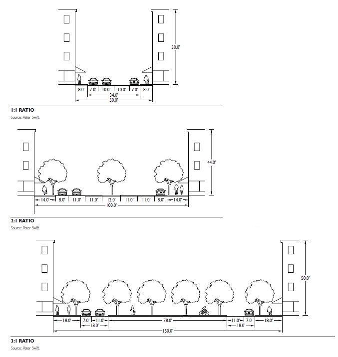
STANDARDS
Conventional thoroughfare design standards are based primarily on A Policy on the Geometric Design of Highways and Streets (AASHTO 2001) and previous editions. Thoroughfare types include arterial, collector, and local streets, in urban and rural contexts. They are described in terms of vehicle mobility and access; arterial streets are almost exclusively dedicated to vehicular mobility. However, the language used to define these thoroughfare types is not complex enough to properly describe a walkable environment. For about 50 years, transportation design literature has described pedestrians as “friction” or “interference.” This further supports vehicle dominance in many traffic design techniques.
Recent design publications from recognized national engineering organizations, including the American Association of State Highway and Transportation (AASHTO), Institute of Transportation Engineers (ITE), Transportation Research Board (TRB), and others, have begun to focus more attention on the nonmotorist and to develop evolving walkability design strategies. Local and state departments of transportation have also begun to develop context-sensitive design approaches.
LAW AND REGULATION
When working with nonstandard design guidelines, liability of the owner of thoroughfares must be considered. Governmental immunity is preserved through the adoption and enforcement of design guidelines. Therefore, jurisdictions should adopt standards by law for pedestrian-friendly streets. If the design is approved as an exception to adopted regulations, there may be some liability exposure, even if there are substantial citations and cases referenced. If the jurisdiction has a single development that needs pedestrian-friendly street design standards, in most cases the adopted ordinance can have provisions exclusive to that development. It is also important to refer to state law when making these decisions.
If the street is in private ownership, the reviewing jurisdiction’s scrutiny can address only the operation and maintenance of public utilities, along with emergency and public vehicle access. Because streets must accommodate the needs of utilities and emergency responders, the jurisdiction can have some limited influence in the design of the street, which could create a legally confusing situation. For example, if an accident victim on a narrower street sues the private owner and the public entity, both parties can be at a disadvantage. A clear establishment of the public right-of-way as public property, along with design criteria adopted by ordinance, may avoid these ambiguities and potential legal battles.
DESIGN ELEMENTS
Narrow, pedestrian-friendly streets are best suited to mixed-use, walkable neighborhoods. Therefore, it is important to understand the elements that inform street design.
Building Enclosure
Building enclosure—the relationship of street and buildings—defines urban space. Analysis of enclosure and urban space is important for achieving a certain aesthetic for the scale, comfort, character, and use of the street as a public room.
The aesthetic of a pedestrian-friendly street relies partly on how the public space is defined by buildings. Building enclosure is defined by the ratio of building separation to building height. For example, a building 50 feet (15.2 meters) high that is 150 feet (45.7 meters) from the building across the street has a ratio of 3:1. Building ratios of 1:1 to 4:1 generally require narrower streets. Ratios approaching 6:1 may lose a perceptible sense of enclosure and should be avoided.
Amenities
The walkability of a street also relies on comfort and safety. Street trees, awnings, arcades, and conditions where at least one side of the street is in shade in the summer all help protect pedestrians from the sun and elements. Because narrower streets have slower vehicular traffic, noise, accident frequency, and accident severity are reduced.
Streets that are accommodating to pedestrians enhance overall street liveliness. Shoppers are attracted to stores when vehicles travel slower and their occupants can look into the windows; thus, economic vitality is enhanced as well.
When choosing to include pedestrian-friendly streets in a design, establish a connected network of streets. This helps disperse traffic and still gives emergency vehicles a number of ways to respond to an incident. Narrower streets are not recommended for cul-de-sac and branchlike thoroughfare patterns.
PARKING LOT DESIGN
Parking lots should offer direct and easy access for people walking between their vehicles and the building entrances. Pedestrians usually walk in the aisles behind parked vehicles; aisles perpendicular to the building face allow pedestrians to walk to and from the building without squeezing between parked cars. Walking areas should be graded to prevent standing water.
Where possible, parking lots should be designed to have reduced paved areas, to minimize runoff problems, and to provide areas for trees and other vegetation.
Provide access for fire rescue and transit vehicles as well as safe and efficient circulation routes. Accessible design requires designating parking spaces and curb ramps near building entrances.
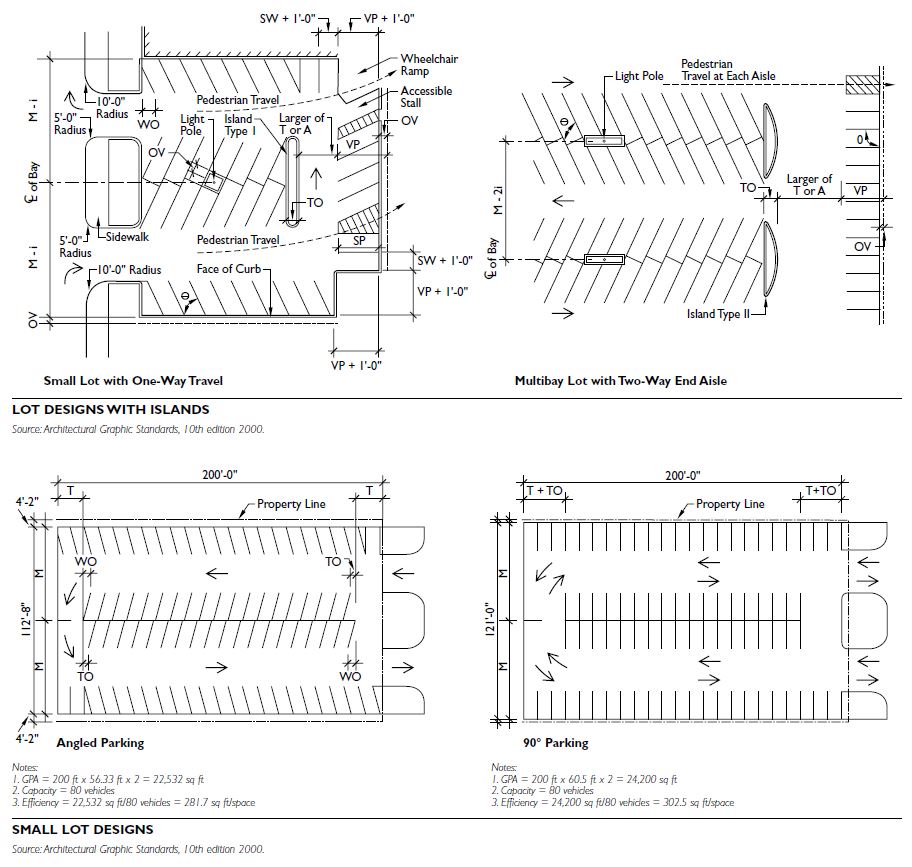
90 degrees
A parking lot designed with 90-degree spaces offers the most space per vehicle. 90-degree angles create an efficient lot. A full parking lot with these spaces looks clean, organized, and deliberately geometrical. You should implement this particular design if your business is expected to have clients for long periods of time.
Parking lots with spaces that are 90 degrees tend to function better for locales** where the public will stay parked for hours.** This is because 90-degree spaces have the highest difficulty in entering and exiting. This particular design is not suited for a business with a quick turnaround.
60 degrees
This particular design is the most common of all because it allows for wider parking spaces and lanes. This means that vehicles will have more room to traverse the parking lot and also settle on a space.
60-degree angles make more room for traffic lanes. Cars will be able to navigate the parking lot with ease. Meanwhile, getting in and out of a lane is a more streamlined process. A 60-degree slant allows for a vehicle to enter and exit a lane with minimal effort.
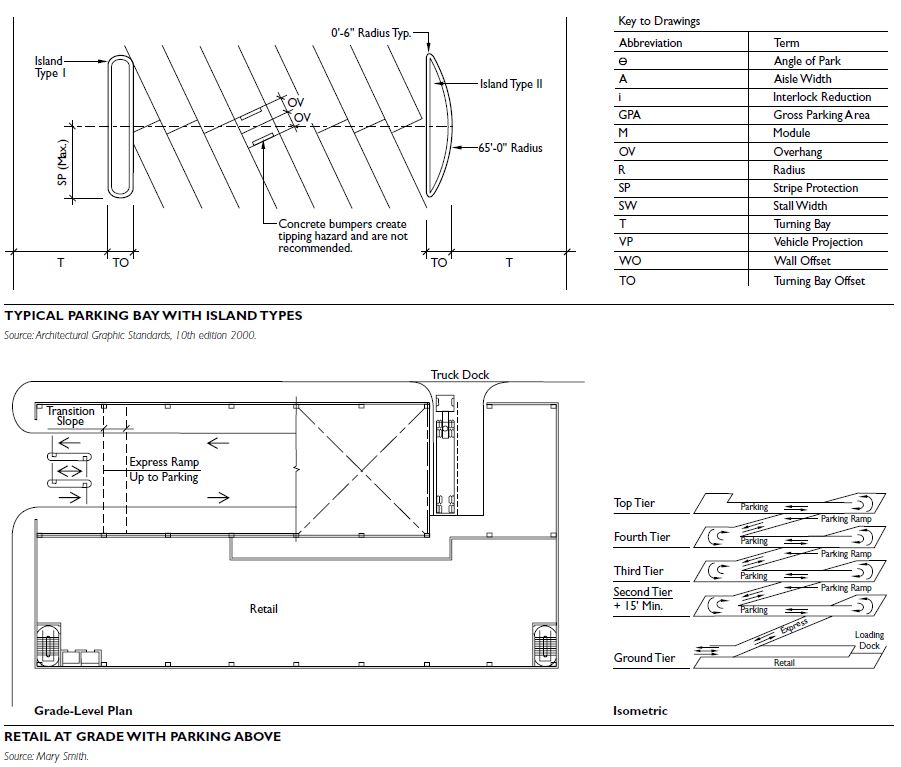
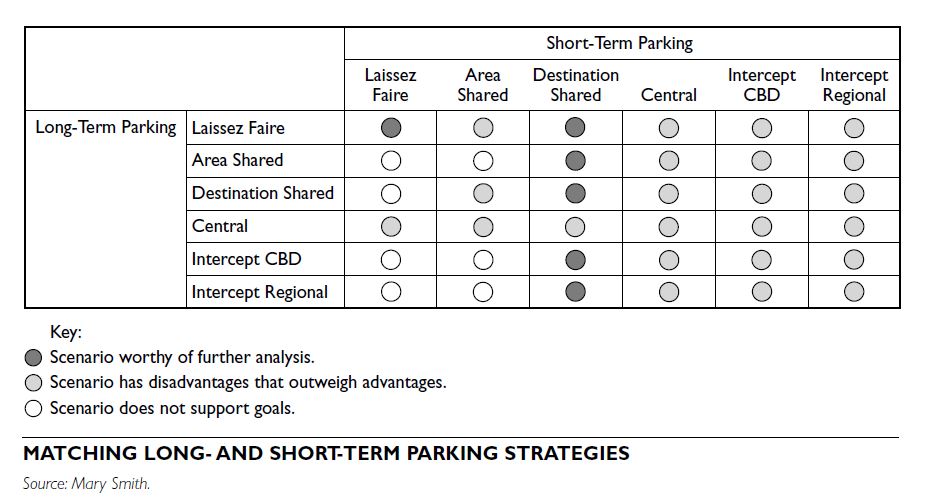
ON-STREET BIKEWAYS
On-street bikeways bring enormous benefits to both the cycling and noncycling public. Bikeways create opportunities to incorporate exercise into one’s daily routine, and bring air, noise, and water quality benefits. They use public dollars efficiently by reducing road maintenance costs and increasing the carrying capacity of the transportation system. Bikeways improve safety for all users; bicyclists feel they have a safe space on the road and tend to be more law-abiding, and motorists are placed at greater ease knowing where bicyclists are apt to be. Bikeways also help motorists to be aware of the presence of bicyclists and their right to be on the road.
Bikeway planning and implementation can be relatively simple and inexpensive, as when a public works agency includes bikeways as part of new road- ways or restripes a roadway with bicycle lanes during a routine resurfacing. Bikeways can also be complicated and costly, particularly in built urban environments with space constraints. Moreover, the installation of bikeways may not always be desirable from the public’s perspective—for example, if park- ing has to be removed to install bicycle lanes or if traffic must be diverted to create a bicycle boulevard. National guidelines for the planning and design of on-street bikeways are provided through the American Association of State Highway Transportation Officials (AASHTO). Standards for signing and striping of on-street bikeways are found in the Manual on Uniform Traffic Control Devices (U.S. Department of Transportation/FHWA 2003); and many states and local jurisdictions have their own standards and guide- lines. In addition, many localities are developing new innovations in on-street bikeway design, such as shared lane markings (San Francisco; Gainesville, Florida; Denver), bicycle-only traffic signals (Davis, California), colored bicycle lanes at intersections (Portland, Oregon), and innovative bicycle boulevard treatments (Berkeley, California). The Association of Pedestrian and Bicycle Professionals (APBP) provides information on emerging on-street bikeway designs.
Specific issues need to be addressed in the design of on-street bikeways:
TYPES OF BIKEWAYS
Bicycle Lane
A bicycle lane is that portion of the roadway designated by 6- to 8-inch (15.24- to 20.32-centimeter) striping and bicycle pavement markings for the exclusive or preferential use of bicycles. Bicycle lanes are typically provided on collector and arterial streets. Bicycle lanes can be implemented by:
Bicycle lanes may be implemented through stand- alone bikeway projects, roadway construction or reconstruction, and routine roadway resurfacing.
Some streets have circumstances that make bicycle lane installation difficult. These circumstances include:
If bicycle lanes are deemed unfeasible, alternative improvements may be substituted, examples of which are described below. Other potential treatments include providing a bicycle lane in only one direction, such as in the uphill direction on a steep slope; using shared lane markings, as cities like San Francisco are doing; or directing cyclists to a parallel bikeway.
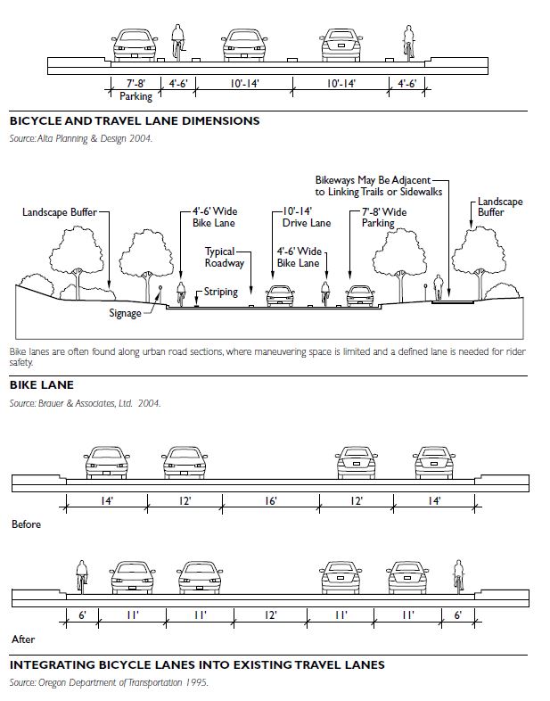
Bike Route
A bike route, also called a shoulder bikeway, is a street upon which the paved shoulder, separated by a 4-inch (10.2-centimeter) stripe, is usable by bicycles, although
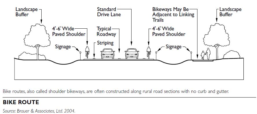 auto parking may also be allowed on it. These bike- ways are typically provided on rural roadways.
Signed Shared Roadway
Signed shared roadways are bikeways without sepa- rated bicycle lanes. Bicyclists and motorists are expected to share the outside lane. There are three variations: extra-wide curb lane, bicycle boulevard, and signed bike route.
auto parking may also be allowed on it. These bike- ways are typically provided on rural roadways.
Signed Shared Roadway
Signed shared roadways are bikeways without sepa- rated bicycle lanes. Bicyclists and motorists are expected to share the outside lane. There are three variations: extra-wide curb lane, bicycle boulevard, and signed bike route.
Extra-Wide Curb Lane
An extra-wide curb lane is a wider-than-normal curb- side travel lane provided to give extra room for bicycle operation where there is insufficient space for a bicycle lane or shoulder bicycle lane. Wide curb lanes have proven to be as safe as bicycle lanes; however, they often do not attract bicycle users, particularly novice or family bicyclists, and thus do little to increase bicycle use in a community.
Bicycle Boulevard
On a bicycle boulevard, bicycles and motor vehicles share the space, which does not have marked bicycle lanes. The through movement of bicycles is given priority over motor vehicle travel on a local street. Traffic calming devices are used to control traffic speeds and discourage through trips by motor vehicles. Traffic control devices are designed to limit conflicts between automobiles and bicycles, and favor bicycle movement on the boulevard street. Typically, bicycle boulevard treatments are designed for local or collector roadways with relatively low volumes of traffic.
Bicycle boulevard design treatments continue to emerge and are highly complementary to traffic calming programs and projects, safe routes to school projects, and other neighborhood desires. However, the impact on through-traffic movement from traffic calming devices can be a point of controversy.
Signed Bike Route
A signed bike route is a bikeway upon which guide signing is placed to direct bicyclists to a destination or another bikeway. Signed connections are used on local, low-traffic streets where bicycle lanes or bicycle boulevards are not needed and on and around major recreational cycling destinations. They should not be used as a substitute for appropriate treatments on collectors and arterials but may work well for short connections and in coordination with a comprehensive bikeway network.
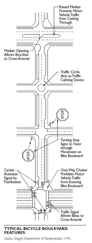
Traffic Signal Allows Bikes to Cross Arterial
BIKEWAY SELECTION AND NETWORK DEVELOPMENT
The appropriate treatment for on-street bikeways depends on motor vehicle traffic volumes, speeds, street width, topography, presence and use of on- street parking, and type of traffic (e.g., presence of freight traffic.) The selection approach varies considerably from jurisdiction to jurisdiction; for example, communities, such as Corvallis, Oregon, provide on- street marked bicycle lanes on all collector and arterial streets, and a few communities use only wide curb lanes and signage. Guidance on methodologies to select appropriate bikeway types is provided in Bicycle Facility Selection: A Comparison of Approaches (King, 2002) available through the National Bicycle and Pedestrian Information Clearinghouse.
A number of communities (e.g., San Francisco; Cambridge, Massachusetts; Chicago; and Gainesville, Florida) strive to provide a comprehensive bikeway network through a combination of bicycle lanes, neighborhood bicycle boulevards/routes, and off-street shared paths, as developed through a bicycle master planning process. This is clearly the most effective way to increase bicycle use and improve safety. For example, Portland, Oregon, has implemented an extensive network of more than 180 miles (290 kilometers) of onstreet bicycle lanes and boulevards. As a result, bicycle use has increased more than 200 percent on its down- town bridges, and bicycle commuting has more than doubled, according to local counts and the 2000 U.S. census. Some of Portland’s neighborhoods have bicycle commute mode shares of more than 4 percent. The increase in bicycle usage has been in lockstep with the increase in bikeway facility mileage, while the number of bicycle-motor vehicle crashes has remained flat.
MULTIUSER TRAILS
Contemporary trail planning at the local and regional levels focuses on creating integrated trail systems that accommodate a range of users, including walkers, hikers, bicyclists, and inline skaters. Trails that accommodate these most common uses are the focus here. On a more limited basis, mountain bike, equestrian, and off-leash dog trails are also provided in local and regional trail systems. In northern climates, winter-use trails for cross-country skiing, dog sled- ding, and skijoring are also common. Off-highway vehicle trails and snowmobile trails are specialized trails common to state-level trail systems. Although not specifically considered here, planners should consider these important types of trails when planning trail systems at the local and regional levels.
FACTORS IN TRAIL PLANNING
Recreational Value
Contemporary trail system planning places great emphasis on the recreational “value” of an individual trail and the trail system as a whole. Preference studies clearly indicate that the vast majority of trail users are seeking a recreational experience while using trails; fitness, transportation, and commuting are secondary concerns. Trails offering a high-quality recreational experience are those that:
The notion of a trail’s recreational value inherently affects community planning and development. Planning for trails following greenways through private developments and public open spaces is considerably different from planning for trails that follow a roadway right-of-way. Whereas greenway-based trails may be more difficult to implement, the value of those trails to the community far exceeds the challenges they present. Communities with success in integrating these types of trails into their system plan often advertise them as key aspects of the city’s built form and quality of life.
Skill Level
One of the important factors in developing a trail system plan is recognizing the broad needs and skill levels of individual trail users. This is especially the case with bicyclists, in which the skill level varies considerably, as follows:
Experienced riders. Generally use their bicycles for fitness or transportation. Speed, convenience, and directness are important factors in route selection. Although they are comfortable riding in traffic, adequate operating space is important to safe riding and avoiding confrontations with motor vehicle operators.
Recreational riders. Typically use their bicycles for recreation and fitness, less so for transportation. These riders tend to avoid busy roads with higher traffic speeds, unless there is a defined area for bicyclists, such as a wide shoulder or a designated bikeway. These riders are generally comfortable riding on local streets and busier trails.
Youth and children. Tend to be slower and less confident than adults. Children use trails for recreation and getting to key destinations in the community, such as schools, convenience stores, parks, and recreational facilities. Residential streets with low motor vehicle speeds are acceptable, but trails are preferred by this group (and their parents).
Trail systems should be planned to accommodate the least skilled bicyclists while still being of interest to the most skilled. Also, trails that are designed to accommodate bicyclists will also be suitable for walkers and inline skaters.
Accessibility
The level of accessibility varies between trail types. In general, the level of accessibility should be consistent with the user expectation, as well as applicable law. In application, this means that multiuse hard-surfaced trails, as classified here, should be accessible to the majority of the population wherever possible. This typically means grades of less than 5 percent.
Accessibility as it relates to nature trails focuses on creating “like experiences” over uniform accessibility. There is often an expectation by the public that these trails will range from easy and accessible to difficult and strenuous. Trail opportunities within each trail system should be planned for the majority of citizens, recognizing that not all trails will be accessible to all people. Clearly marked trailhead and trail signage is critical to users selecting trails that suit their needs and abilities.
TRAIL CLASSIFICATIONS
The distinction between trail types, or classifications, is as much about their location and recreational value as it is about technical design considerations. The user experience and skill level associated with differ- ent types of trails greatly affects the value of the system to residents and the degree to which a trail or system of trails will be used. The classifications purposefully correlate with desired user experience, with emphasis on the quality of experience.
The classifications are meant to be guidelines, not rigid standards. Each community must refine and apply them to suit their specific needs. The following provides an overview of the classifications for the most common trail use associated with a typical local and regional trail system.
Destination Trail
This type of trail is often a destination unto itself due to its location and recreational appeal. Destination trails are located within a greenway, natural area, parkway, or designated trail corridor and typically accommodate walkers, bicyclists, and inline skaters.
In areas of low- to modest-use levels, a shared use trail is common. In higher-use areas, separating walkers from bicyclists and inline skaters is also common. The essential characteristics of a destination trail emphasize harmony with a natural, sometimes park- like setting and the user’s recreational experience. The trail allows for relatively uninterrupted pedestrian movement to and through a natural area, the community, or larger park and open-space system. Destination trails also separate trail users both physically and psychologically from vehicular traffic and are, therefore, suitable for all skill levels.
General Design Characteristics
Creating a compelling recreational experience that includes a variety of landscapes and community set- tings is a design priority in the design of destination trail. Providing an interesting sequence of visual experiences is often as important as the length of the trail to many users.
Asphalt/bituminous is a common surfacing mate- rial for destination trails and can be used in most climates. Crushed compacted aggregate surfacing is also acceptable for less traveled trails or those in a natural setting. Concrete surfacing is suitable where long term durability and/or patterned textures are desired. Concrete is not as well suited in climates where freeze-thaw cycles can create problems with expansion and contraction of crack control joints, which can make for a much rougher ride.
Trail width varies considerably depending on the anticipated level of use, length, and setting. Local trails within a neighborhood are typically a minimum of 8 feet (2.4 meters) wide. A 10-foot-wide (3-meter- wide) trail is the desired minimum for primary corridors that traverse through a community or region following a major greenway, parkway, or designated trail corridor. A 12-foot-wide (3.7-meter-wide) trail is becoming more common for regional facilities in a metropolitan area where use levels are high.
One-way directional trails are becoming more common along major greenway or parkway corridors in large urban areas. These trails are used to increase capacity, improve safety, and provide a more pleas- ant visitor experience. Each directional trail is a minimum of 8 feet (2.4 meters) wide, with 10 feet (3 meters) preferred. A 10-foot (3-meter) minimum green boulevard between trails is typical, with 20 feet (6 meters) or 30 feet (9 meters) preferred.
The design speed varies from 10 to 15 mph (16.1 to 24.1 kph) in a neighborhood setting up to around 20 mph (32.2 kph) for major trails. Most riders pedal at around 12 to 16 mph (19.3 to 25.8 kph), with elite recreational riders maintaining as high as 22 to 25 mph (35.4 to 40.2 kph). Generally, trails should be designed for around 20 mph (32.2 kph) to accommodate most riders. Any higher design speed can encourage riders to go too fast, and then be unable to react to others on the trail. (Most accidents are caused by collisions with other trail users, not trail design.)
Sight distances on all trails should be a minimum of 50 feet (15.2 meters), with 100 feet (30.5 meters) or more preferred. Longer sight distances may be required when trails traverse long open stretches or encounter steeper gradients where higher riding speeds occur.
Trail gradients should average less than 5 percent to be considered an accessible trail, with 3 percent preferred. Eight to 10 percent gradients are accept- able for moderate distances. Grades in excess of 10 percent should be avoided.
The cross-slope on a trail should be around 1.5 percent. Excessive cross-slope (beyond 2 percent) is too noticeable and an annoyance to walkers. Super- elevating trails greater than 3 percent can cause accessibility issues and are generally not recommended.
Overhead clearance on trails should be a minimum of 10 feet (3 meters). A shoulder area of grass or compacted gravel should be a minimum of 2 feet (0.6 meters) on each side, with 4 feet (1.2 meters) being desirable prior to grade changes or physical impediments.
Other design characteristics include:
Linking Trail
The significant difference between linking (connector) and destination trails is their location, which significantly affects their recreational value. Whereas destination trails emphasize a recreational experience in a natural open space or parklike setting, linking trails emphasize safe travel for pedestrians to and from parks and around the community. In general, linking trails are located within road right-of-ways and utility easements. Once a linking trail enters a park, it technically becomes a destination trail, due to
the setting and higher recreational value. Linking trails still provide notable recreational value, but significantly less than destination trails, due to vehicular traffic (safety, noise, distraction) and a less visually attractive setting. Like destination trails, linking trails are suitable for all skill levels.
General Design Characteristics
Providing a safe connection between specific destinations is a design priority. Recreational value remains important, but the setting is generally less compelling than that of a destination trail. Asphalt/bituminous is a common surfacing material for linking trails, though crushed compacted aggregate surfacing is also accept- able. Concrete surfacing is suitable where long term durability and/or patterned textures are desired. Concrete is not as well suited in climates where freeze-thaw cycles can create problems with expansion and contraction of crack control joints, which can make for a much rougher ride.
Trail width varies considerably depending on the anticipated level of use. Local trails along a roadway are typically a minimum of 8 feet (2.4 meters) wide. A 10-foot-wide (3-meter-wide) trail is the desired minimum for primary corridors where parks, schools, public facilities, and business districts are located. Along busy thoroughfares with extensive trail destinations, a trail along both sides of the road is more common.
The design speed for linking trails is fairly consistent with destination trails. Ten to 15 mph (16.1 to 24.1 kph) is suitable for a neighborhood setting, and up to around 20 mph (32.2 kph) for trails along major thoroughfares. Overall trail speeds are often lower than destination trails due to the number of roadway crossings and driveways, which force bicyclists to slow down. Generally, trails should be designed to a similar standard as destination trails.
Sight distances on all trails should be a minimum of 50 feet (15.2 meters), with 100 feet (30.5 meters) or more preferred. Longer sight distances may be required when trails traverse long open stretches or encounter steeper gradients where higher riding speeds occur.
Trail gradients should average less than 5 percent to be considered an accessible trail, with 3 percent preferred. Eight to 10 percent gradients are accept- able for moderate distances. Grades in excess of 10 percent should be avoided.
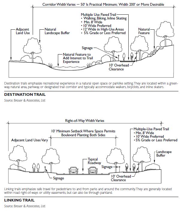
Nature Trail Nature trails are located in greenways or natural resource-based parks and open spaces where experi- encing the natural environment is the primary objective, along with exercise and quiet space. The character, length, and level of difficulty of nature trails can vary significantly from open prairie and wood- lands to mountainous terrain.
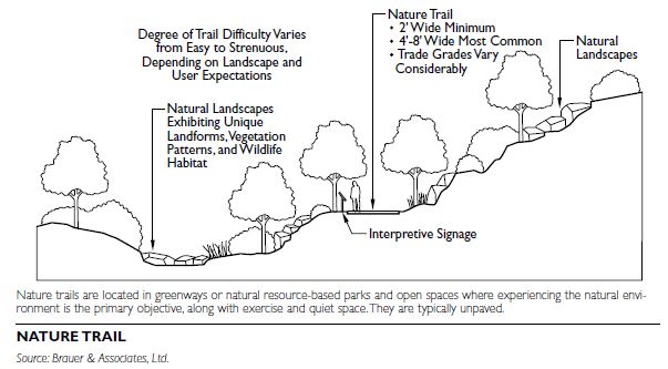
General Design Characteristics
The overarching design theme for nature trails is sim- ple and intimate, in keeping with the setting. Also key is to provide “like” experiences for people of varying physical abilities. Shaping the trail layout to conform to the landscape and creating a sequence of visual experiences is critical to creating a successful nature trail. Notable landscape features, topographic changes, and vegetation patterns are all used to create appealing visual experiences that engage the trail user and cause them to linger and return.
Nature trails are generally surfaced with natural soils, turf, crushed aggregate, or other selected natural material. Grades on nature trails will vary, perhaps considerably. Ruggedness and strenuous trails are often part of the desired experience: easy trails have gradients of 3 to 5 percent; moderate trails have gradients of 8 to 10 percent; steep and strenuous gradients are often over 10 percent.
Sustainability of nature trails is a major design con- cern. Gradients, soil erosion, and compaction all affect trail stability and sustainability. “Rolling grade” design techniques that factor in alignments, tread grades, sideslopes, tread crests and dips, and erosion prevention are commonly used to create sustainable nature trails.
Trail width varies considerably depending on the anticipated level of use, length, and setting. Remote trails are often footpaths a couple of feet wide. Trail widths of 4 to 8 feet (1.2 to 2.4 meters) are common in local and regional park settings.
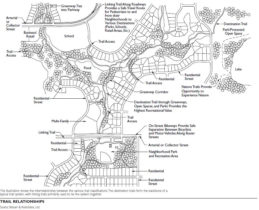 Additional design characteristics include:
TRANSIT SYSTEMS
The transit planning process can be condensed into four primary elements of a continuous feedback and review cycle: systems planning, service planning, service implementation, and performance measurement.
Metropolitan planning organizations (MPO) estimate total travel demand. Demand is based on the evaluation of land uses and accepted trip generation rates. Following estimation of total transit market demand, transit trips are distributed across the region connecting suburban nodes, regional activity centers, and the urban core. Based on this market assessment, trips can be differentiated as follows:
MODE SELECTION/MODAL TOOLBOX
Applying the proper service to each market segment requires an understanding of the operating character- istics of the available modes and their fit within the transportation system. Transit modes are differenti- ated by average speed, carrying capacity, availability as measured by average distance between stops (called stop spacing), and the level to which exclusive rights-of-way are required to realize optimum operations from each mode.
BUS TRANSIT
Bus transit involves using rubber-tired vehicles that, for the most part, operate on fixed schedules and routes on a roadway. According to the American Public Transportation Association, buses comprise the majority of the total U.S. public transportation fleet. For many communities, bus transit is the only fixed-route transit option available. Diesel, gasoline, battery, or alternative fuel-powered engines contained within the vehicles power them.
TYPES OF SERVICE
There are three primary types of bus service: local, express, and limited-stop. These services can be used alone or in combination with other transit modes.
Local Service
With local service bus transit the vehicles stop every block or two along the route. This is the most common type of bus transit service.
Express Services
Express services connect a number of areas with the central business district (CBD) or other major destinations. These services typically operate during the morning and afternoon-evening peak travel hours. Express routes often use freeways or major arterials and make fewer stops along the way to make more predictable, faster trips.
Limited-Stop Service
Limited stop service is a combination of local and express service. The stops may be several blocks to a mile or more apart.
Bus Rapid Transit
Bus rapid transit (BRT) is a type of limited-stop service. It provides high-speed bus service regardless of traffic conditions and frequently operates in a dedicated right-of-way. BRT combines the advantages of rail transit with the flexibility and lower capital cost of bus service. BRT systems often make use of transit signal priority systems to minimize delays at signalized intersections. BRT is addressed in more detail elsewhere in this book.
BUS RAPID TRANSIT
Bus rapid transit (BRT) is a flexible, rubber-tired rapid transit mode that combines stations, vehicles, service, running-ways, and intelligent transportation system (ITS) elements into an integrated system with a positive identity and a unique image. In many respects, BRT is “rubber-tired” light-rail transit, but it has greater operating flexibility and potentially lower cap- ital and operating costs than light rail. BRT can be especially desirable in large cities, where passenger flows warrant frequent service, and there is a sufficient presence of buses to justify dedicated running ways. To support ridership, this normally requires an urban population in the United States that exceeds 750,000 and a downtown employment base of at least 50,000 to 75,000.
The common types of BRT service are conventional radial routes between a city center and outlying areas (as in Pittsburgh), extension of a rail rapid transit line (as in Miami), and a mostly peak-period commuter express operation (as in Houston).
BRT Features
The primary features of BRT are:
Few existing systems have all six BRT features, although many have several. Exclusive running ways (bus lanes or busways) are the most common feature; off-vehicle fare collection is the least common.
RAIL TRANSIT
Rail transit technology includes a wide range of options. The American Public Transportation Association (APTA) categorizes rail transit into three general groups:
Here, light rail and streetcar/tram systems are defined and discussed separately. These various rail technologies differ as to:
Location. They can operate on exclusive right- of-way, semiexclusive right-of-way (tracks that cross streets at grade), or on shared right-of-way (tracks embedded in a roadway).
Speed. Vehicles on shared right-of-way travel with the speed of the rest of traffic; vehicles in exclusive right-of-way can operate at higher speeds.
Passenger volume. The number of passengers per hour a system can carry is a function of the size and number of vehicles and the frequency of trips.
Cost. The cost of a system is a function of infra- structure and facility costs.
Unlike the universal acceptance of the AASHTO “Green Book” for highway design, there is no corresponding national standard for transit. Most transit agencies have agency-specific or even project-specific transit system design criteria. When planning for transit, become familiar with local standards.
COMMUTER RAIL
Also called regional rail, suburban rail, or metropolitan rail, commuter rail typically provides service between a central city and the surrounding suburban areas for short-distance travel. The engines are typically electric or diesel-powered, and the cars are hauled by a locomotive or are self-propelled. Specific station-to-station fares and only one or two stations in the central city characterize these systems.
HEAVY RAIL
These systems use high-speed and rapid-acceleration passenger rail cars that operate singly or in multicar trains on fixed rails. They run on rights-of-way sepa- rate from all other vehicular and foot traffic. High-platform loading is used, and these systems have capacity for a heavy volume of traffic, making them well suited for high-volume commuter trips. Sophisticated signaling systems are often in use.
LIGHT RAIL
Light rail transit (LRT) is an electric railway system characterized by its capability to operate single cars or short trains along exclusive rights-of-way at ground level, on aerial structures, in subways, or, occasionally, in streets. LRT systems board and dis- charge passengers at low-level platforms located either at track or car-floor level. They operate in medium- to high-volume commuter corridors.
STREETCAR/TRAM Streetcars are metropolitan electric railway vehicles designed to fit the scale and traffic patterns of the neighborhoods through which they travel. Streetcar vehicles are narrower and shorter than other rail cars typically seen in service in the United States. They run in mixed traffic and, except at stops, accommodate existing curbside parking and loading. These systems serve as medium- to high-volume circulator services and often serve as collectors and distributors for regional transit systems
INTERMODAL AND MULTIMODAL TRANSIT FACILITIES
Intermodal facilities allow for transfer between transportation modes. Multimodal facilities also provide transfer opportunities but, in addition, serve each mode independently, often functioning as a transportation hub for major components of the system. Intermodal and multimodal facilities help a community achieve a balanced transportation system, one that supports all transportation needs.
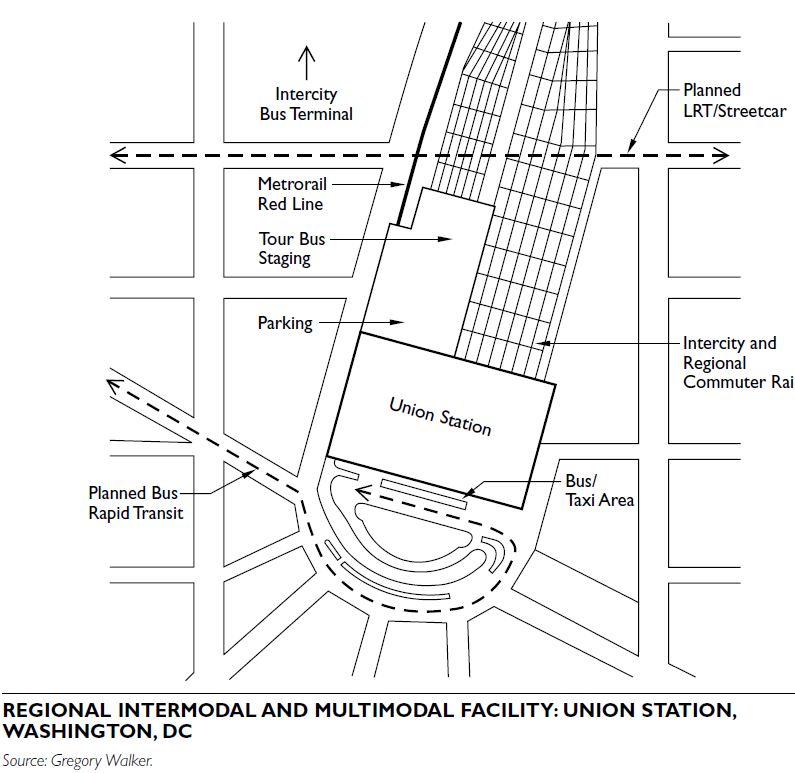 MODES SERVED
Public transit generally consists of bus and rail technology serving a variety of local and regional trip types. Presented in ranked order in consideration of frequency of stops and carrying capacity, the following are relevant to the discussion of intermodal and multimodal facilities:
Details on bus transit and rail transit are included elsewhere in this section of this book. While not applicable to urban transit, intercity bus lines (e.g., Greyhound) and intercity rail lines (e.g., Amtrak) often interface with local transit and therefore are significant to the discussion of intermodal and multimodal facilities.
ADJACENT COMMUNITY CHARACTER AND FORM
When planning new or expanding existing intermodal and multimodal facilities, community character and form must also be taken into account. In relatively high-density urban environments, intermodal and multimodal facilities generally serve as a transfer point between radial trunk services and local distribution modes. Many are developed as mixed-use facilities. In Tacoma, Washington, SoundTransit and the City of Tacoma converted a former freight trans- fer facility into a regional intermodal and multimodal station. Light rail, commuter rail, and two bus lines serve the facility. Amtrak and Greyhound also have facilities nearby. A large-scale urban intermodal and multimodal facility is Union Station in Washington, DC, one of the busiest surface transportation passenger facilities in the world. Union Station provides connections to Washington DC’s Metrorail, Virginia, and Maryland commuter rail services, Amtrak, intercity buses, tour services, local buses, and taxis. In addition, the facility is a regional shopping and entertainment center, featuring more than 100 shops, restaurants, and bars, and a movie theater.
In suburban environments, it is particularly important to consider adjacent land uses when planning for an intermodal and multimodal transit facility. The level of traffic and noise generated from high-activity facilities may be more compatible with commercial uses than with residential uses.
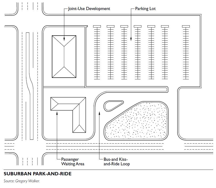
FACILITY TYPES
In their most basic form, intermodal and multimodal facilities usually provide for passenger transfer between two or three modes. The suburban park-and-ride serves as a centralized access point for bus or rail commuter service. In low-density areas, it is more cost-effective for the transit agency to provide high-frequency service from a central location. In areas of moderate density or where sufficient land is not available for commuter parking, high-capacity transit services rely on a system of feeder buses and passenger drop-off as the primary means of system access.
High-density urban environments usually accommodate a varied mix of facilities, each designed to serve a specific function. Union Station in Washington, DC, includes nearly every mode and trip type. Also in Washington, DC, L’Enfant Plaza allows commuter rail passengers to transfer to either bus or heavy rail, and heavy rail passengers are able to transfer between lines.
WASTE MANAGEMENT
Solid waste is regulated under Subtitle D of the Resource Conservation and Recovery Act (RCRA). The primary goal of RCRA is to encourage solid waste management practices that promote environmentally sound disposal methods and maximize the use of materials recovered from waste and foster resource conservation. The U.S. Environmental Protection Agency (U.S. EPA) implements RCRA.
RCRA Subtitle D strongly encourages states to develop and adopt statewide solid waste management plans that attempt to assess solid waste generation and management within the state and describe the state’s anticipated direction toward man- aging its waste during a specific time period. The U.S. EPA’s role has been limited to setting the minimum regulatory requirements that states must follow in designing their plans and to approving plans that comply with these requirements. The development of state plans is voluntary. The great majority of rules that regulate municipal waste are state environmental agency rules adopted under enabling laws that address solid waste. RCRA has resulted in a significant decrease in the number of landfills and an increase in recycling since the 1970s.
ROLES AND RESPONSIBILITIES
Decision makers must develop the best possible alternatives for local solid waste management by ensuring that all local, state, and federal legislative factors, as well as private enterprise and concerned members of the larger community, are accounted for in the planning process. Considering the complexity and legal requirements of solid waste management, it is important to clarify the roles and responsibilities of government units, the private sector, and citizens in managing the country’s solid waste.
Municipal Government
Municipal governments historically have had the responsibility to coordinate, provide, or otherwise ensure that a collection system for refuse, recyclables, and landscape waste is in place for municipal residents. Municipal governments: offer a range of public services, from curbside collection to drop-off services; contract for services partially or entirely to nonprofit or for-profit service organizations; or have residents privately arrange for services. Four common types of contractual arrangements typically used for collection within municipalities exist:
Municipal service. Municipal employees collect waste with municipally owned equipment.
Municipal contract. One or more private haulers operate under contract to the municipality. The municipality collects fees or taxes, then pays the waste hauler(s) for contracted services.
Franchise contract. The municipality grants or sells hauling privileges (franchises) to one or more private haulers for waste collection services in the municipality. The fees are collected directly from the customer by the waste hauler(s).
Private contract. Under private contract collection, the individual resident or business contracts directly with the private waste hauler for waste collection services. The only involvement by the municipality is the possible licensing of solid waste haulers.
In order to effectively manage collection programs, municipal governments may want to develop and adopt local ordinances to encourage or facilitate specific solid waste programs. For example, St. Louis County, Missouri, encouraged municipalities to incorporate recycling in their contracts with local haulers by developing a model bid specification that included recycling in the base contract agreement. Nationwide, a number of municipalities and counties require haulers to provide recycling and incorporate “pay-as- you throw” pricing. Municipal governments should work in partnership with other units of government, industry, and citizens to effectively plan and implement an integrated waste management system consistent with the county, regional, or municipal solid waste (MSW) management plan. An integrated program includes recycling, landscape waste management (e.g., composting), special pickups, household hazardous waste management, public education regarding waste disposal and diversion options, direct or transfer waste hauling for disposed material, and final disposal at landfills or incinerators.
State Government
A number of states provide assistance in developing and implementing a county or municipal integrated waste management program by providing technical and financial assistance, issuing regulations, and developing education programs. The state agencies, such as the state environmental protection agency, pollution control agency, or department of environmental quality, may provide technical assistance on collection, hauling, processing, marketing, disposal, or procurement. The agencies may also encourage certain types of local waste management practices by making solid waste grant funding available. For example, the Illinois EPA made funds available to counties for solid waste planning studies in the mid-1990s. Other state agencies established recycling grant programs that address local recycling needs.
Federal Government
The federal government, through the U.S. EPA, takes a role in waste management by establishing national goals, developing education programs, providing technical and financial assistance, and issuing regulations. The agency also has a role in establishing a framework for state and local planning; setting mini- mum standards for solid waste facilities; and encouraging the manufacturing industry to design products and packaging for effective waste management, as well as to use secondary materials in manufacturing. Areas where federal action is likely to occur include interstate transport of waste and a national materials usage policy.
Private Enterprise
Waste management companies, including local haulers, recyclers, processors, end markets, and disposal facilities, have a responsibility for planning and implementing waste management systems consistent with their local solid waste management plan. Private enterprise should work in partnership with units of government, industry, and citizens to effectively plan and implement integrated waste management systems and to educate the public.
Citizens
Citizens, as well as private and public entities, have a responsibility to learn how their purchase, usage, handling, and disposal of products and materials affect the waste management system. Citizens should assume responsibility for the waste they create and attempt to recognize the true costs of disposing of their waste. Citizens should strive to stay apprised of local solid waste management initiatives; provide input throughout the planning and implementation process; and make educated decisions regarding the local management of solid waste.
INTEGRATED WASTE MANAGEMENT
The U.S. EPA’s integrated waste management hierarchy includes the following three components, listed in order of preference:
The strategy is: first generate as little waste as possible, then recycle as much of the waste as possible, and, finally, properly dispose what is left over.
Source Reduction
Source reduction is the practice of generating less waste. It includes numerous practices:
Recycling
Recycling includes methods of capturing residential, commercial, and industrial materials that are then subsequently remanufactured into new products. This includes recycling paper, glass, aluminum, and other materials commonly considered recycling, but also includes the amount composted by composting facilities. According to the U.S. EPA, in 2001, the United States recycled and composted between 25 and 30 percent of the solid waste generated.
Landfills
Landfills are engineered ground vaults with a con- trolled method to encapsulate waste that prevents leachate and other pollutants from escaping into the environment. Landfilling is the predominant method of disposing waste in the United States, accounting for about 55 percent of the total waste generated.
Incineration
Incineration is the burning of refuse to reduce its volume and weight. The U.S. EPA estimates that the volume of waste is reduced by 90 percent and the weight of waste is reduced by 75 percent with incineration. Combustion accounted for about 15 percent of the total waste generated in the United States in 2001.
Transfer Stations
Transfer stations are facilities where waste from smaller vehicles, such as garbage trucks that pick up in neighborhoods and at businesses, is consolidated and placed on larger vehicles, such as trains, semi- trailers or barges. Because many remaining landfills are located several miles from a number of population sources, waste is more cost-effectively transferred in larger vehicles than in smaller packer trucks.
WASTE MANAGEMENT PLANS
Waste management plans prepared by units of government generally include the recommended ingredients of source reduction, recycling, waste to energy, and land- filling. Plans are developed that include special studies on a region’s current and future waste generation and established management goals. Waste planning studies typically include a state or local government’s waste reduction goals, as well as the methods to achieve those goals through recycling, composting, and state and local legislation to encourage or mandate recycling. Special studies are often performed, such as household weekly waste setout quantities, burn barrel usage, food waste generation, construction and demolition debris generation, commercial recycling opportunities, and impacts of hauler ordinance changes.
WASTEWATER
Wastewater is potable water that has been used within a community for various purposes.
DOMESTIC WASTEWATER
Wastewater for residential uses, such as showers, sinks, washing machines, and sanitary facilities (including those in commercial buildings and institutions), is domestic wastewater. It is readily treated within a standard wastewater treatment facility.
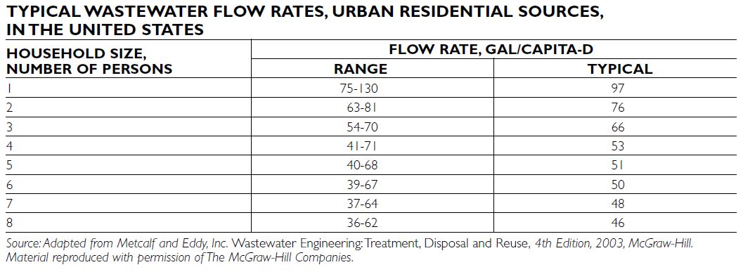
INDUSTRIAL WASTEWATER
Industrial wastewater is water that has been used for manufacturing purposes and may have specific contaminants related to the source industry. These contaminants, which may be organic compounds, inorganic compounds, or metals, make industrial wastewater difficult to treat using domestic treatment processes.
Municipal officials and regulatory agencies evaluate each industry prior to allowing discharge of its wastes to the treatment plant. A municipality may require the industry to pretreat the waste to remove components that may inhibit or interfere with biological processes at the wastewater treatment plant. In some cases, a municipality may not allow the waste to be discharged to the municipal system even after pretreatment if the waste is hazardous. The industry will then have to contract with a hazardous waste facility for hauling and treating that waste. This can be an expensive proposition. It is important to deter- mine whether the wastewater treatment facility has the capability to treat the waste from a proposed industrial site, prior to any development.
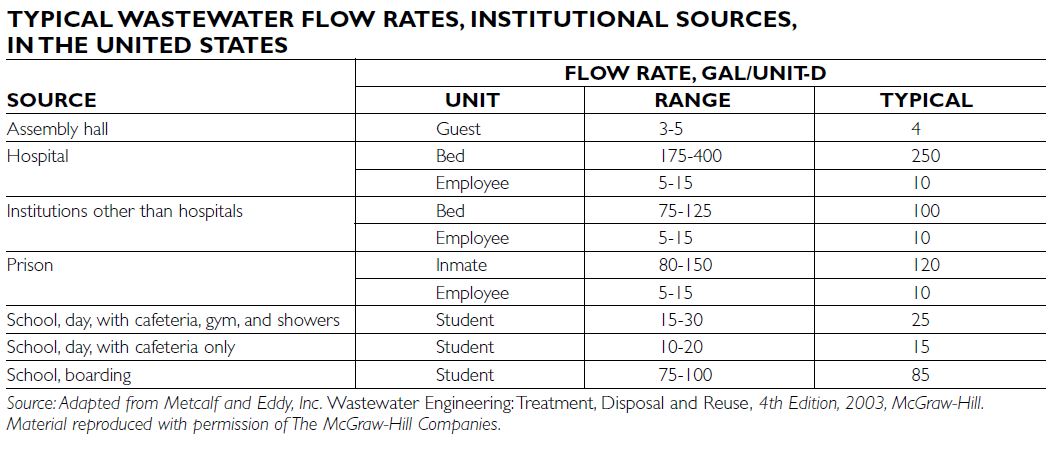
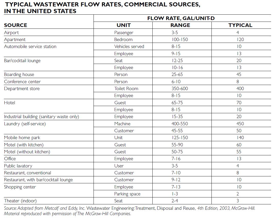
INFLOW AND INFILTRATION
Inflow and infiltration (I&I) is water that enters the collection system (sewer pipes) through various direct and indirect methods. Infiltration is groundwater entering through open joints or cracks in pipes. Inflow is rainwater that enters the system through roof leaders, basement sump pumps, or other access points. I&I may exceed the capacity of a wastewater treatment plant and collection system. It should be reduced or eliminated to the extent possible and cost-effective.
Frequent in-line television (TV) camera inspection can evaluate infiltration and determine the location of open joints and cracked or broken pipes. These can then be repaired by injecting grout into the joints and cracks, replacing the portion of broken sewer, or lining the pipe with a plastic or resin material. These processes are effective but can be costly and must be evaluated on the basis of cost/benefit. Smoke testing can easily identify inflow. The technician places a smoke bomb in the sanitary sewer and then watches where the smoke exists through roof leaders, basements, and other areas where sump pumps might be connected to the sanitary sewer system. The municipality then notifies the property owner to redirect the flow to a storm sewer. It is important to understand the adverse effect of stormwater entering a separate sanitary sewer system.
QUANTITIES AND FLOW RATES
For residential wastewater sources, quantities are typically determined on the basis of population. For planning purposes, a two-person household is expected to use between 63 and 81 gallons per capita per day, and a six-person household is expected to use between 39 and 67 gallons per capita per day. Flow rates for a particular community depend on the availability and cost of supplied water, and the economic and social climate of that locale.
Flow rates from commercial, institutional, and industrial facilities are based on a variety of factors. For example, the flow rate from a hotel is typically based on a volume of water per guest; and for an apartment it is typically based on a volume of water per bedroom.
Various flow rates must be evaluated to ensure that both the collection system and treatment process will have sufficient capacity. A development could possibly be delayed or disapproved if the flow rate is greater than either the capacity of the treatment plant or collection system. If a sewer line or a pumping station is too small in the immediate area of the pro- posed project, developers sometimes pay or share the costs of increasing the size of the line or capacity at the station.
CHARACTERISTICS AND TESTING
Wastewater has physical, chemical, and biological characteristics that must be understood and monitored. The relationship and magnitude of wastewater characteristics are community-specific and depend mainly on the geographical location, commercial and industrial makeup, and the source of potable water.
Physical characteristics include solids, turbidity, and temperature. Chemical components include pH, chloride concentration (especially for coastal communities), nitrogen, phosphorus, sulfur, metals of various types, and a variety of inorganic and organic compounds. Biological characteristics include microorganisms, such as bacteria, protozoa, and fungi.
Wastewater treatment plants should monitor influent characteristics on a daily basis. This is typically required by permit, but it is also the only way a treatment plant can be successfully operated.
Biochemical Oxygen Demand Test
Organic (carbon-containing) constituents are measured by the biochemical oxygen demand (BOD) test. BOD measures quantity of oxygen used in the bio- chemical oxidation of organic matter in a specified time and temperature (20°C). This test mimics what occurs in a modern wastewater treatment plant and in natural water systems. The typical time for a BOD test is five days—the notation for that test is BOD5. Some BOD tests will be run for 20 days, and are noted as BOD20. For scientific purposes, some BOD tests extend beyond 20 days, referred to as the ultimate BOD (BODU).
BOD measurements are required by a plant’s operating permit and are used to permit and monitor industrial discharges to a treatment facility. BOD rep- resents the oxygen demand from both carbonaceous and nitrogenous compounds. Some states use carbonaceous BOD as the permit requirement. Carbonaceous BOD (CBOD) is always less than the total BOD.
Chemical Oxygen Demand Test
Another test used to measure organic components is chemical oxygen demand (COD), which is a quantitative measure of the amount of oxygen required for the chemical oxidation of carbonaceous (organic) material in wastewater. This test takes two hours to perform and is more useful for monitoring and con- trol than the BOD test.
Solids Testing Both inorganic and organic solids are also measured. They are typically classified as total solids (TS), volatile solids (VS), total suspended solids (TSS), and volatile suspended solids (VSS).
REGULATIONS
Clean Water Act
The 1972 Federal Water Pollution Control Act Amendments (the Clean Water Act) has had the great- est impact on wastewater treatment and receiving water quality. The goal of this act was to make the waters of the nation “swimable and fishable.” To accomplish this, the act established the National Pollutant Discharge Elimination System (NPDES), which is a permitting program for all dischargers based on uniform minimum categorical standards. In most cases, authorized states issue NPDES permits. The act was amended in 1987 to strengthen the water quality regulations by providing changes in permit- ting, adding substantial financial penalties for violations and emphasizing identification and regulation of toxic pollutants in sewage sludge. NPDES permits take into account the capability of a stream to assimilate discharges.
Sewage Sludge Regulations
Sewage sludge is the by-product of the wastewater treatment process. This material can have significant contaminants and a negative impact on the environment if not treated and disposed of properly. In 1993,sewage sludge regulations (40 CFR Part 503) were passed, which established national standards for pathogen, vector attraction, and metal concentration reduction for sludge (biosolids), which could be used as a fertilizer or soil amendment. This regulation defines two classes of biosolids, A and B. Class A can be used for all land application, including home use as a fertilizer. Land application of Class B biosolids is strictly regulated, and they cannot be used for home application.
Total Maximum Daily Load
The U.S. EPA put the Total Maximum Daily Load (TMDL) rule into effect in 2002. A TMDL is the maximum amount of a pollutant that a water body can receive without negatively affecting the water quality to below the standard set for that body. States, territories, and tribes set water quality standards. They identify the uses for each water body, such as drinking water supply, recreation, and fishing, and determine the scientific criteria to support that use.
A TMDL is the sum of the allowable loads of a single pollutant from all discharges into that specific body of water, including individual wastewater treatment plants, surface runoff, industrial discharges, and aerial deposition. The calculation must include a mar- gin of safety to ensure the water body can be used for the purposes the state has designated. The calculation must also account for seasonal variation in water quality. Through the TMDL program, regulators establish a waste load allocation for the individual dischargers of that pollutant. The TMDL program enables effluent credit-trading programs, such as the nitrogen credit- trading program in Connecticut. Information on the Connecticut program is available on the state’s Web site.
STORMWATER RUNOFF AND RECHARGE
Stormwater management encompasses the broad field of managing runoff from precipitation events to control or mitigate a range of issues:
The information here focuses on the issues of recharge of precipitation to groundwater and treatment of runoff to reduce pollutant load delivery to receiving waters.
STORMWATER AND WATER QUALITY
Stormwater runoff, particularly from urban land uses, is widely viewed as one of most significant contributors to water quality impairment (Burton and Pitt 2002). Many believe the cause of impairment is a result of pollutant delivery to receiving waters. While pollutants in stormwater runoff are certainly ubiquitous and frequently at concentrations that do contribute to water quality impairment, the impact on water quality from reduced ground- water recharge, accelerated stream channel erosion, and increased flooding is also part of the stormwater problem.
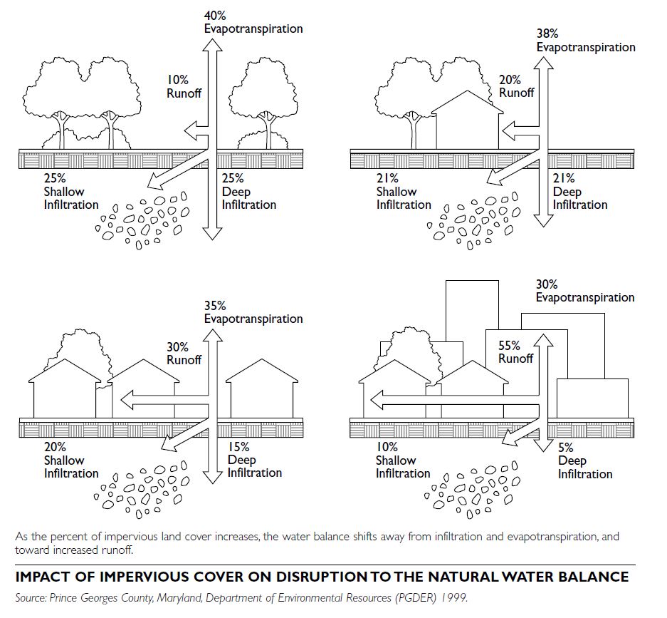
PRINCIPLES OF STORMWATER MANAGEMENT
Two fundamental principles must be understood in order to gain a grasp of the wide topic of stormwater management.
The first is how the basic water balance changes as a result of altered land use. The second is that precipitation varies widely, and the probability of a given precipitation event governs how that event can be effectively managed.
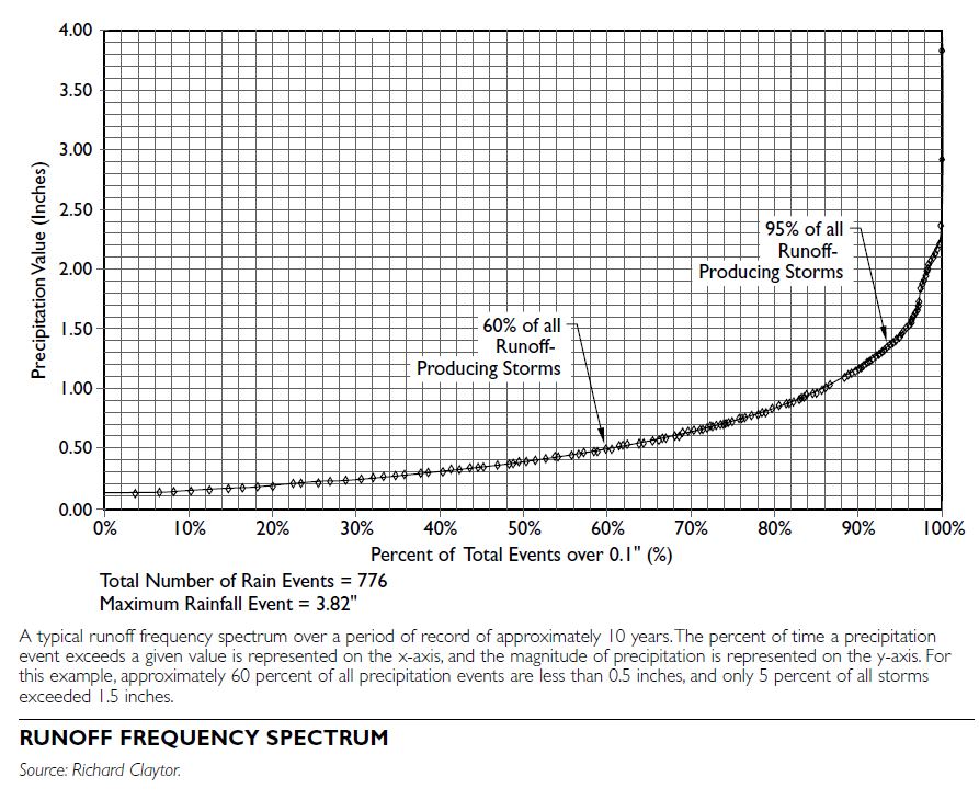
Water Balance
In relatively undeveloped or rural areas, total precipitation is divided into three principal components:
evapotranspiration, infiltration, and runoff.
The quantity of each of these variables depends on the amount of precipitation, climate, vegetative cover, soils, land slope, amount of impervious area, and the characteristics of precipitation events, such as intensity of rainfall. As land is altered from less intensive to more intensive uses, impervious cover increases, and the relative balance of these three variables is changed. The most dramatic effect is that runoff volume increases and infiltration decreases.
The consequence of more runoff occurring more frequently is an acceleration of overland and channel erosion, increased pollutant washoff from the land to receiving waters, and increased flooding frequency, leading to property damage and potential threats to public safety. Decreased infiltration reduces the amount of groundwater recharge and leads to a loss of total water volume to supply streams, wetlands, ponds, and lakes during dry weather. In many regions, streams that were perennial under more rural conditions become intermittent as a watershed develops. An assessment of the distribution of precipitation characteristics must be the initial step in developing any stormwater management approach.
Precipitation Conversion to Runoff
It is also important to understand how precipitation is converted to runoff. Many models and methods exist to describe this phenomenon; the basic variables include the amount and intensity of precipitation and the infiltrative characteristics of the land surface. More intense rainfall, more impermeable land surface, and steeper land surface all will generate more runoff. In nearly all conditions, the smallest storms do not produce any runoff. Even a parking lot can absorb a small amount of precipitation before runoff occurs. Referred to as the initial abstraction, this is the volume of storage contained within the land surface prior to runoff occurring.
The runoff frequency spectrum depicts only runoff-producing events, or those precipitation events greater than a given amount, usually between 0.1 inches and 0.2 inches. When addressing stormwater, the main concerns are usually the amount and rate of runoff. The distribution and magnitude of the runoff frequency spectrum vary as a function of long- term climate and rainfall characteristics. Regions that receive little total rainfall or, conversely, a disproportionate number of tropical storms will each have a different curve. To effectively manage stormwater runoff across this broad spectrum, different curves must be produced for different regions. Once the runoff frequency distribution is calculated and under- stood, criteria can be applied to address the various issues identified above.
STORMWATER RUNOFF RECHARGE
Recharge is the volume of precipitation that infiltrates into underlying soils, which supports and maintains groundwater levels, and is not either directly released as evapotranspiration or conveyed downstream as runoff or interflow. Interflow is an “in-between” category in the water balance, where precipitation is initially infiltrated below the surface but then flows more laterally toward a stream, river, or lake at a much slower rate than direct runoff. Some interflow may ultimately become runoff, evapotranspiration, or recharge.
Simplifications of complex conditions in the natural environment often must be developed and applied to understand stormwater movement. However, it must be recognized that some of the time, conditions will vary. For example, those events that produce little or no runoff and also occur most frequently may contribute to recharge or may support evapotranspiration, depending on the time of year. In colder climates, evapotranspiration is dramatically reduced during the winter months. A small rainfall event occurring in November will likely contribute to recharge, whereas the same-sized rainfall event in June or July will often be transpired directly by vegetation and never reach the groundwater.
Recharge across the Runoff Frequency Spectrum
The amount of recharge needed to mimic natural conditions varies. The best approach is to rely on what occurs naturally and derive criteria to meet that condition. If the natural rate of recharge is 50 percent of the precipitation volume, strive to infiltrate half the total precipitation volume. This is accomplished by setting a design criterion to ensure that half the total long-term precipitation is directed back into the ground.
If practices are sized to capture and infiltrate a 0.4- inch precipitation event, as shown in the illustration, then slightly more than half of the total long-term precipitation will be recharged. All rainfall will infiltrate for storms up to 0.4 inches. This comprises approximately 25 percent of the total long-term precipitation volume. A correspondingly smaller percentage of each storm larger than 0.4 inches will be infiltrated. For example, storms that are between 0.7 and 0.8 inches will recharge only about 60 percent. If in an average year 3.3 inches of precipitation falls from storms in this range, only about 2.1 inches of this would be infiltrated by a practice designed to infiltrate 0.4 inches. Adding all of these together, the total annual average infiltration volume would be approximately 20.9 inches, which is approximately 54 percent of the total annual average precipitation and slightly more than the 50 percent target. Unfortunately, data on the amount of annual recharge that occurs at a given location are not always available; more importantly, natural recharge varies dramatically as a function of soil type. Clay soils have far less recharge capabilities than sandy soils. Consequently, some management programs use a soil-type recharge criterion. The approach involves determining the average annual recharge rate based on the prevailing hydrologic soil group (HSG) present at a project site from the Natural Resources Conservation Service (NRCS) Soil Surveys. HSG is an NRCS designation given to different soil types to reflect their relative surface permeability and infiltrative capability (U.S. Department of Agriculture, Natural Resources Conservation Service 1986).
Group A Soils: Low runoff potential and high infiltration rates. They consist chiefly of deep, well-drained sands or gravels with infiltration rates greater than 0.3 inches/hour.
Group B Soils: Moderate infiltration rates (0.15 to 0.30 inches/hour). They consist chiefly of soils with fine to coarse textures.
Group C Soils: Low infiltration rates (0.05 to 0.15 inches/hour). They have fine textures that impede the downward movement of water.
Group D Soils: High runoff potential with very low infiltration rates (0.0 to 0.05 inches/hour). They consist chiefly of clay soils.
The method was developed based on the amount of annual recharge that occurs as a function of HSG type and uses the following predevelopment recharge percentages to be assigned based on NRCS soil types.
| Hydrolic Soil Group | Annual Recharge (percent of annual Soil Group precipitation) |
|---|---|
| A | 41 percent |
| B | 27 percent |
| C | 14 percent |
| D | 7 percent |
The objective of the criterion is to mimic the aver- age annual recharge rate for the prevailing hydrologic soil group(s) at a new development project. Therefore, the recharge volume can be determined as a function of annual predevelopment recharge for a given soil group, average annual rainfall volume, and amount of proposed impervious cover.
GUIDELINES FOR APPLYING A STORMWATER RECHARGE CRITERION
Several constraints and opportunities must be considered when implementing a recharge strategy. These include understanding the array of physical limitations, identifying some cautions on infiltration of runoff from certain land uses, and having a firm understanding of the methods and techniques used to foster infiltration of stormwater runoff. The most current federal, state, and local regulations regarding the introduction of stormwater into groundwater must be reviewed. Some methods are classified as underground injection wells, which require different permits from typical stormwater management approvals.
Physical Limitations
Physical stormwater recharge limitations include the following:
Land-Use Limitations
Land uses with the potential to generate high concentrations of soluble pollutants that can threaten groundwater quality, if infiltrated directly, include the following:
Carefully evaluate these threats prior to employing groundwater recharge techniques. In many instances,
complex pretreatment measures can be used to reduce and/or remove pollutant and then safely apply recharging techniques.
RECHARGE TECHNIQUES
There are a variety of stormwater practices that meet the recharge objectives:
WATER SUPPLY
A water supply system consists of one or more of the following components, from initial supply source to delivery:
SOURCES OF SUPPLY
Surface Water
Surface water is the water source most commonly used by large cities. Different surface water resources function in various ways.
When determining the types of surface water sources to be used, public perception is a critical component to consider. Pollution in rivers, multiple uses of lakes and rivers, the ability to desalinate the ocean, and perception issues regarding the potability of reclaimed wastewater are all issues of concern. When considering a new surface water source, con- ducting an extensive education and public involvement program is often necessary to gain acceptance.
Groundwater
Groundwater is an extremely important water supply source. It is the principal source for approximately 48 percent of the U.S. population (AWWA 1995). Groundwater sources can be relatively simple to develop and often require little or no treatment. They can also be found within the community area and require no more land than a site for the well and pump house, often less than a 50-foot-by-50-foot piece of land. If groundwater wells are located within an urbanized area, a wellhead protection zone should be adopted to protect the well field from contamination. Business and industrial activities located within the groundwater protection zone can be regulated to prevent activities that could contaminate the well field.
One variation of groundwater is aquifer storage and recovery (ASR). ASR involves the injection of domestic water into drilled wells, either modified existing wells or newly developed wells, and then withdrawn during the high-demand season. ASR wells serve as giant reservoirs below the ground and allow a community area to balance the winter and summer flows without construction of reservoirs and pipelines to support the high summer demands.
WATER DEMAND
Several factors influence water demand, including climate, community size and density, types of customers (residential, commercial, industrial), fire flow, cost of water, and level of water conservation.
Demand Averages
The national average daily demand is 160 gallons per capita per day (Merritt et al. 2003). Water demand is calculated using computer models that take into account variables such as average demand by types of customers, community size and density, and climate variations. For individual developments, the developer typically informs the water agency what their estimated water use will be. Another approach is to look at historical usage and project that forward.
Peaks
Water demand varies over the course of a day, month, and year. The amount of water used on the highest consumption day of the year is known as the peaking factor. A peaking factor is applied to deter- mine maximum daily demands. Typical peaking factors range from 1.1 for communities that are heavily industrialized, have high density, little outside summer water usage, and a strong water conservation program, to more than 2.0 for suburban areas with large lots and mostly residential services. In hot climates with extensive outdoor irrigation, the peaking factor may exceed 2.5.
Fire Flow
The Insurance Services Office (ISO) classifies a community for insurance rating purposes on the basis of a maximum fire flow credit of 3,500 gallons per minute (gpm) flow from the water system. Fire flow requirements are set for various building types, and water systems need to meet those demands. In general, overall water systems are evaluated for fire flow capability assuming fire flows of 3,500 gpm for commercial and industrial areas, and 1,500 gpm for residential areas.
WATER QUALITY REGULATIONS
Federal All U.S. public water systems serving at least 15 connections or 25 people must comply with the Safe Drinking Water Act (SDWA) of 1974 and its 1986 and 1996 amendments. The SDWA defines a contaminant as any physical, chemical, biological, or radiological substance or matter in water. Maximum contaminant levels (MCL) state the maximum permissible level of a contaminant in water delivered to any user of a public water system.
State and Local
Some states and municipalities have adopted standards and water quality goals for the water they serve their customers that are more stringent than the SDWA. However, no state or municipality may adopt a standard less stringent than those required by the SDWA.
Many statutes are adopted by states to both implement the Safe Drinking Water Act and to address other issues such as the Uniform Fire Code (UFC). The UFC describes the fire flow requirements for various dwelling types.
DEVELOPMENT STANDARDS
Most water providers have adopted development standards that prescribe the required sizing, type, location, and materials to be used in the development of water systems. Typically, the local governing body from which compliance is required adopts these standards.
WATER RIGHTS
To be able to access a source, a water provider must hold water rights to that source. There are two basic systems of water rights in the United States:
Riparian Doctrine
In the riparian doctrine, the theory is that those owning land adjacent to a body of water should share the water. This represents a sharing concept, as opposed to a right to a specific amount of water.
Doctrine of Prior Appropriation
The doctrine of prior appropriation states “first in time, first in right.” A permit is granted for a specific amount of water, and the water right is based on the date of the permit or when the use first occurred. The doctrine follows two basic principles: priority use and beneficial use.
NEW WATER SUPPLY SOURCES
Developing new surface water sources for urban water supply is a complex process. Involving the public, securing all necessary state and federal permits, securing funding, designing and constructing facilities, and implementing the system can take 10 years or longer. Development and population growth projections are necessary to help best determine the next increment of supply to meet estimated future demand.
WIRELESS INFRASTRUCTURE
Wireless infrastructure includes the towers, antennas, radio equipment, and associated structures that establish a wireless communications network. Currently, more than 50 percent of U.S. households use mobile phones, and, by 2007, that number will have increased to 80 percent.
Wireless carriers establish and expand their service by constructing base stations or by contracting with an infrastructure company to construct base stations or install their antennas on an existing structure.
DEMAND FOR WIRELESS SERVICE
The demand for more and better wireless service is on the rise. To meet this demand, wireless carriers must try to achieve coverage throughout the community, including residential areas. The challenge facing municipalities throughout the country is twofold: to enable wireless deployment in a responsible way, and to develop zoning regulations and comprehensive plans to accommodate this rapidly changing environment. Because of the continual changes to this technology, municipalities should periodically review their telecommunications regulations to ensure that they meet current and future community demand for wireless services.
COMPONENTS OF WIRELESS INFRASTRUCTURE
The components of wireless infrastructure are essentially the wireless handset, a specialized radio set commonly referred to as a mobile, or “cell,” phone, and a base station, a transmission facility in a fixed location designed to communicate with the wired telephone network or with mobile or portable communications devices. Although appearance varies widely, generally, base stations contain the following components:
Emergency generators or an array of batteries serve as backups to enable uninterrupted service during a power outage.
In addition, where appropriate or applicable, base stations may have access roads or driveways; fencing around the compound, to deter public access; landscape planting or screening to mitigate visual impacts; and signage containing contact information, as well as the antenna structure registration (ASR) number if the structure is registered with the Federal Communications Commission (FCC).
REGULATIONS
The construction, siting, and design of wireless infra- structure are regulated on the federal, state, and local levels. Typically the regulated elements include the following:
Federal Regulations
Several federal laws and agencies have jurisdiction over issues related to telecommunications.
The Telecommunications Act of 1996. The main purposes of this act are to clarify the level of regulation that local governments can apply to service providers and to provide for industry- wide competition.
The Federal Communications Commission (FCC). The FCC regulates operational aspects of wireless services, including antenna frequencies, operating powers, and radio frequency emissions. The FCC also regulates towers with antennas through the antenna structure registration (ASR) program.
The National Environmental Policy Act of 1969 (NEPA). All antenna structures must comply with NEPA. In many instances, applicants must conduct an environmental assessment (EA) to investigate all potential environmental impacts and disclose any significant effects that would result. If the EA determines that significant adverse impacts would result, the FCC places all such proposals on public notice for a 30-day public comment period.
The National Historic Preservation Act of 1966 (NHPA). Infrastructure providers must ensure that structures do not have an adverse effect on historic properties, including buildings, districts, structures, objects, or Native American burial grounds. If there is a potential for impacts on such a resource, the tower applicant must work with the State Historic Preservation Officer (SHPO) to identify actions to mitigate impacts.
The Federal Aviation Administration (FAA). The FAA regulates structures within navigable air- space. Towers above a certain height or within a certain distance of an airport must be registered with the FAA and possibly be marked with lighting or painting. Tower companies submit project proposals to the FAA for evaluation for a determination of “no hazard to air navigation.”
The Occupational Safety and Health Administration (OSHA). OSHA provides regulations to protect the workers who construct, service, or work on or around towers.
State Regulations
On the state level, wireless facility regulations vary, with most states deferring wireless infrastructure siting controls to local governments. However, a few states have enacted legislation that supersedes local regulatory authority to ensure that certain state public policy objectives are met. For example, Washington requires its communities to allow wire- less service providers to place antenna sites in public rights-of-way, and Connecticut has a state-level siting council that reviews applications for antenna sites throughout the state. In addition, some state occupational safety agencies have safety standards that supplement the federal requirements, and many state departments of environmental protection provide regulations that protect wetlands and habitat areas from tower construction impacts.
Local Regulations
Zoning
Nearly all local governments have zoning authority over antenna and associated infrastructure siting. Zoning regulations typically identify which zoning districts allow for these facilities and establish standards for the size, height, and type of facility, its placement on the property, and any buffering and screening required to mitigate visual intrusion.
Permitting
Wireless facilities siting typically follows a local government’s permit review process, including any requirements for site plan submission and approval. The review process, which is usually a prerequisite for building permit issuance, evaluates the plans to ensure the facility meets all prescribed safety and structural/building code standards.
WIRELESS FACILITIES SITING
In addition to following local zoning regulations, applicants should select sites that are safe, effective, and as visually unobtrusive as possible. Site selection typically involves the applicant identifying the geographic area, or search ring, that will enable the carrier to meet the desired coverage objective while integrating with any existing or planned neighboring sites. The coverage objective is generally based on market demand for new services, enhanced quality, or increased system capacity.
Site selection is often a process of elimination. When looking for coverage, there is usually more than one site that is suitable. However, as the demand for more and better wireless services continues to escalate, particularly in residential areas, the number of sites narrows considerably. This is called capacity. Accordingly, companies select those sites that are most likely to:
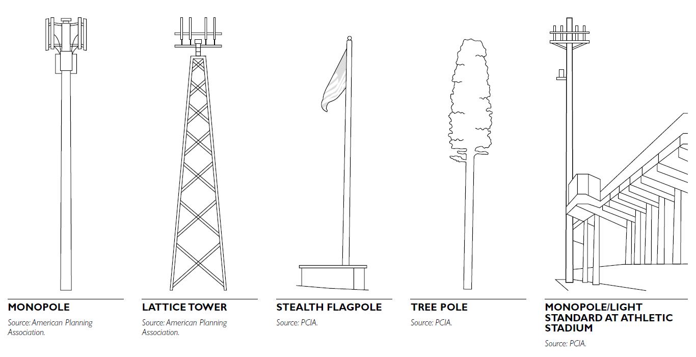 Zoning Review and Approval
In most communities, local governments have jurisdiction over wireless telecommunications siting decisions. The Telecommunications Act of 1996 preserves this authority. However, local government zoning decisions about wireless telecommunications facilities must satisfy certain conditions:
The act also allows applicants to request expedited appeals of zoning denials to both state and federal courts.
MITIGATING IMPACTS OF WIRELESS TELECOMMUNICATIONS FACILITIES
Several steps can be taken to reduce the impact that towers have on a community: - Locate facilities in or around areas of mature vegetation that screen all or part of the facility, thereby reducing its visual impact. - To the extent permitting by federal regulations that govern marking schemes, color the structure to blend in with the surrounding vegetation or skyline. - Plant vegetative cover or constructing fencing at the base of the facility to screen the ground equipment. - Pursue “stealth” options, such as designing the tower or monopole to look like a tree, silo, or a flagpole. - Require low-profile or slim-lined structures where the antennas are installed more closely to the tower, thereby reducing the physical profile of the facility.
TYPES OF PARKS
Contemporary parks and open-space planning focuses on creating systems that respond to local values, needs, and circumstances. The region of the country, physical setting, landscape features, demo- graphics, and socioeconomic characteristics are all determining factors in the form that a community’s park and open-space system will take. In each system, parks and open spaces are defined under various classifications that function individually and collectively to create a cohesive and balanced system.
Successful parks and open-space systems are often planned around distinguishing landscape features or local themes that exhibit the unique qualities of a community. The “city as a park” concept is a common theme, whereby parks and open spaces are key factors in shaping the built form and character of a community. Perpetuating an interconnected latticework of parks, natural open spaces, and trails throughout the community is another theme. Common to all systems is the notion of creating a high-quality living environment through the provision of parks, open spaces, trails, and recreational amenities.
With such a broad spectrum of potential applications, the classifications for parks and open space are necessarily flexible and adaptable to the unique circumstances to which they are applied. The extent to which one type of park versus another is found within a system is determined by local needs and circumstances. In a metropolitan system, emphasis on neighborhood parks, parkways, and large urban parks is common in response to the urban form and distinctiveness of individual neighborhoods. In an outer-ring suburban area rich in natural resources, creating an interconnected system of greenways, parks, and trails may be the desired vision.
PARKS AND GREENWAYS CLASSIFICATIONS
A typical park and open-space system consists of a variety of parks and open spaces defined under various classifications. The classifications presented here are based on consolidating generally accepted professional practices used across the country. They are meant to be guidelines, not rigid standards. Each community must refine and apply them to suit its specific needs. The table provides an overview of the classifications for a typical local park system. Additional references for park and open-space classifications include the National Park, Recreation, Open Space and Greenway Guidelines, published by the National Recreation and Park Association (1995).
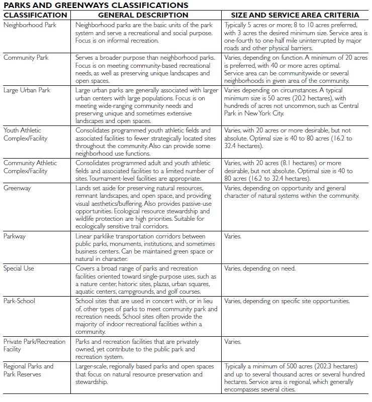
CUMULATIVE PARK SYSTEM ACREAGE STANDARDS
Historically, acreage standards (i.e., optimal number of acres of parkland per 1,000 population) were used, in part, to determine the overall land area necessary to meet community parks and open-space needs. Since the mid-1990s, this broad-brush approach has been deemphasized because it was found to be too arbitrary and not reflective enough of the nuances of park and open-space opportunities and needs associated with individual communities.
The current standard is for each community to develop a park and open-space system plan based on an assessment of its own unique park and open- space system needs and opportunities. A comparison analysis against like cities is still often justifiable, but only as part of larger needs assessment to ensure that a well-balanced system plan emerges based on local circumstances.
NEIGHBORHOOD PARK
Neighborhood parks are the basic unit of the park system and serve a recreational and social purpose. Development focuses on informal recreation. Programmed activities are typically limited to youth sports practices and occasionally games.
General Characteristics
In situations where neighborhood parks are inte- grated into a larger greenway system with interlinking trails, the distance between parks can be expanded to one-half to three-fourths mile (0.8 to 12. kilometers) because greenways and trails provide easy access and these corridors are perceived to be part of the park experience by the user. Development Parameters
The design for each park is uniquely tailored to the neighborhood it serves, rather than the generalized needs of the overall community. The common objective of all neighborhood parks is to bring people together to recreate and socialize close to home. Active, nonprogrammed recreation remains a main- stay of these parks, although contemporary design emphasizes providing a balanced set of amenities that appeal to a broad range of individuals to increase park usage. The general palette of amenities typically found within a neighborhood park includes the following:
COMMUNITY AND LARGE URBAN PARKS
Community and large urban parks are considerably larger in scale and serve a broader purpose than neighborhood parks. The main difference between a community and large urban park is that the latter is often associated with urban settings with large populations. Large urban parks also tend to be larger than community parks in order to provide more park space in a denser populated urban setting. They are especially prevalent in urban areas with limited natural open spaces, such as New York City’s Central Park.
The focus of both types of parks is on meeting wide-ranging community recreation and social needs. The facilities found within these parks are entirely based on meeting defined community needs. Development focuses on both active and passive recreation, with a wide array of programmed activities often being accommodated. Special-use facilities are routinely located within these parks.
This type of park also encompasses unique and extensive landscape features indicative of the region.
Providing respite from the built form is also a major objective of these parks.
General Characteristics
Development Parameters
The design for each type of park is a reflection of the community. The common objective of community and large urban parks is to bring people together to recreate, socialize, and find quiet space. Active, programmed recreation is appropriate in these parks as long as it does not unduly interfere with other activities. As with neighborhood parks, contemporary design emphasizes providing a balanced set of amenities that appeal to a broad range of individuals to increase park usage. The general palette of amenities typically found within these two classes of park includes the following:
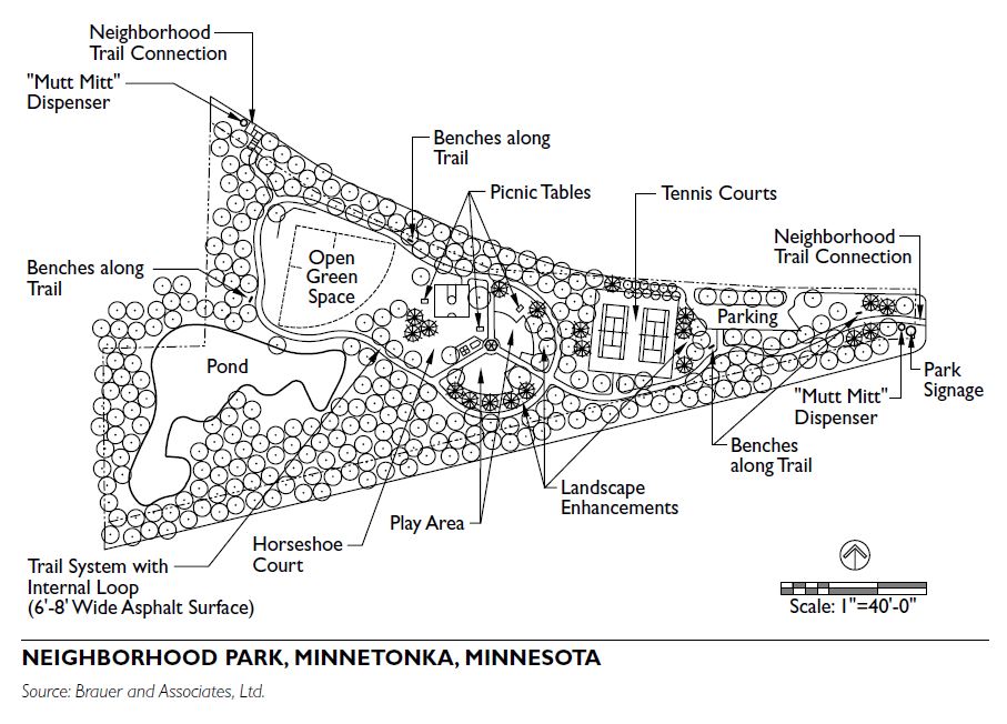
YOUTH AND COMMUNITY ATHLETIC COMPLEXES
Youth and community athletic complexes consolidate athletic facilities to strategic locations within a community to take advantage of programming efficiencies and economies of scale. Consolidation of athletic facilities also allows for a closer association between players, parents, and coaches when at scheduled events. Larger and fewer sites also provide greater conveniences, such as parking, restrooms, and concessions, and the capacity to generate revenue to offset operational and maintenance costs.
Community athletic complexes are most common and serve both youth and adult athletic programs. Youth athletic complexes are more common in larger metropolitan areas where there is enough participation in youth sports to warrant a stand-alone complex. In most cases, athletic complexes are heavily programmed with facilities to maximize land uses and operational efficiency. The type of facilities found within these parks is entirely based on meeting defined community athletic program needs. With ever-changing recreational trends, greater emphasis is being placed on designing athletic complexes to be as flexible as possible without unduly compromising specific uses. As an example, “athletic greens” that can accommodate a variety of field games have replaced single-use facilities. This is largely accomplished through site grading and field lighting placement.
General Characteristics
Development Parameters
The facilities provided at athletic complexes are entirely driven by demand. In communities where the population is not very diverse, a common set of traditional facilities is often appropriate. In larger, more diverse cities, the facility mix can vary widely. In both cases, due diligence is required to ensure the right mix of facilities are provided at a given site.
Facility quality tends to be highest at athletic complexes to accommodate competitive recreational leagues and tournament play. The facilities and amenities often found at athletic complexes include fields and courts for softball, baseball, soccer, foot- ball, lacrosse, basketball, tennis, and volleyball. Regional facilities like hockey rinks are also provided where demand warrants. A greater sensitivity toward providing athletic facilities associated with new immigrant populations is also warranted in many regions of the country.
A variety of support amenities are also appropriate at athletic complexes, including restrooms, concession stands, spectator sitting areas, play areas for children, and picnic areas with shelters. Adequate parking and internal trails are also ancillary requirements. Special-use facilities that serve a specific recreational purpose (i.e., aquatic centers, ice arenas, and skateboard parks) can also be located on athletic complex sites.
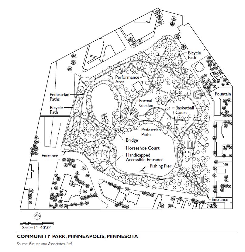
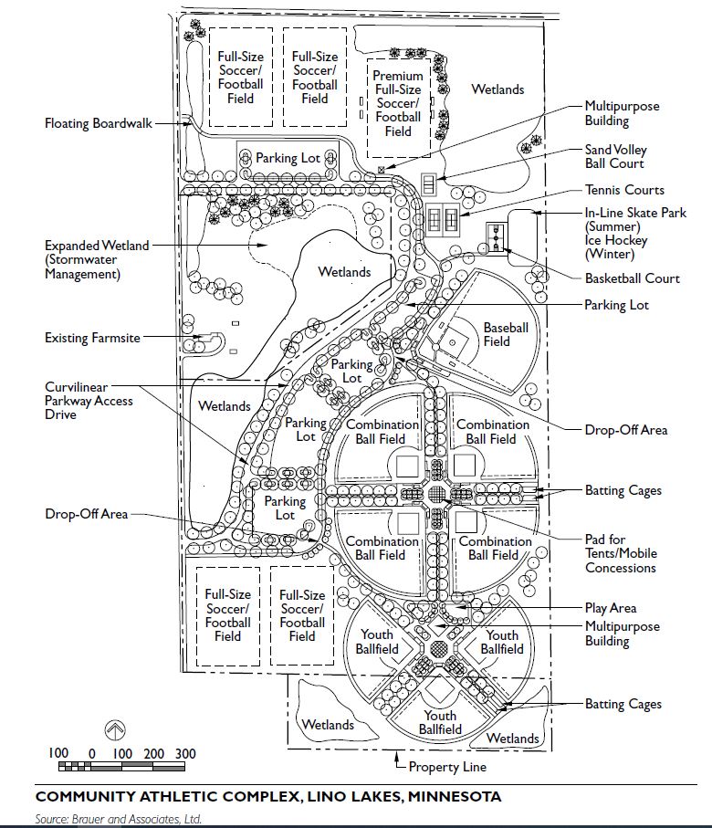
GREENWAYS
Greenways are lands set aside for preservation of natural resources, remnant landscapes, open space, and visual aesthetics/buffering. Greenways also provide passive-use opportunities, most often in the form of trails and, occasionally, nature centers. The key focus is on protecting ecological resources and providing wildlife corridors. Greenways can take various forms. In the broadest application, greenways form a network of interconnected natural areas throughout a community. They function as part of a borderless system that links together parks, natural open spaces, and trail corridors into a latticework of public space. In this context, the line between greenways, parks, trails, and the built environment is purposefully blurred, fostering the “city as a park” concept. Establishing an extensive continuous greenway system requires a close collaborative relationship between the city and development community in order to set aside the land for this purpose.
Greenways can also take the form of a stand-alone land parcel dedicated to open-space preservation. These are often referred to as nature preserves or nature parks and often serve the same basic function as other forms of greenways.
General Characteristics
The baseline criterion for defining greenways is to preserve the highest-quality and most unique landscape features of the city. This most often includes lakes, wetlands, creek corridors, bluff lines, and remnant, relatively undisturbed natural areas exhibiting vegetative communities common to the area. Ecological buffers, which provide physical separation between sensitive or vulnerable natural resources and the built environment, are often integrated into the greenway system as part of the land development process.
Restored landscape, such as an agriculture field transformed back into a prairie, can also be inte- grated into the greenway system. This most commonly occurs as part of a development plan in which restored natural areas are part of an ecologically based stormwater management system.
The width of linear greenways can vary considerably.
Development Parameters
Development within greenways is typically limited to trails, sitting areas, observation areas, and interpre- tive/directional signage. In some cases, nature centers or arboretums are integrated into larger greenways. A combination of multiuse hard-surfaced trails for bik- ing, walking, and in-line skating and nature trails for hiking are found within most greenway systems. In select instances, no development is allowed and the site is set aside for wildlife and community viewing from the periphery.
PARKWAYS
Parkways are best characterized as linear parks that also serve as transportation corridors between public parks, historic features, monuments, institutions, and business centers. They often follow a notable landscape feature, such as a creek or river.
General Characteristics
The length of a parkway ranges from less than a mile to a complete loop around a major metropolitan area. Their width can vary considerably, with 200 feet being the practical minimum, and widths of 1,000 feet or more being common along major parkways.
Landscape planting and ornamental site amenities (i.e., street lighting, site furnishings and other architectural elements) provide the visual cues that distinguish parkways from other thoroughfares. A broad, tree-lined boulevard is a common image of a parkway, as is a linear park along a major river. In keeping with the setting, heavy truck traffic is often, but not exclusively, prohibited along parkways.
Landscape planting can range from a maintained, ornamental character to one that is more natural, or a combination of both.
Development Parameters
Development within parkways is typically limited to roadways and pedestrian trails. Sitting areas and over- looks often augment trails to view a natural or human-made feature. Occasionally, picnic shelters and other standalone park features are accommodated in parkways. Roadway and trailside signage is important.
SPECIAL-USE PARKS
The special-use classification covers a broad range of parks and recreation facilities oriented toward single- purpose or specialized use:
In some systems, certain types of special uses are defined under their own classifications when those occurrences are frequent enough to warrant doing so. For example, an urban square classification is some- times used in major urban communities to accommodate public plazas, courtyards, and formal sitting areas.
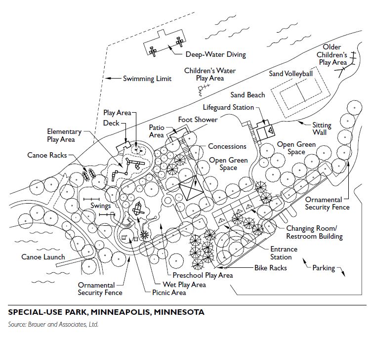
General Characteristics and Development Parameters
The park-school classification pertains to school sites used in concert with, or in lieu of, other classes of parks to meet community park and recreation needs. In most cases, these sites are best suited for youth athletic facilities for both school district and community-based recreational programs. Park-school sites also often provide the majority of indoor recreational facilities within a community.
To a lesser degree, school sites can also be used to service neighborhood park needs. The limiting factor is that most of these sites are heavily programmed for active uses and school buildings. This often leaves little space to accommodate neighborhood-focused amenities and create an aesthetically appealing set- ting that would draw families into the site.
Development Parameters
The design for park-school sites is driven first by the needs of the school district, with most of the facilities designed to accommodate physical education and sports programs. The facilities provided at school sites are most often consistent with the youth athletic complex and neighborhood park classifications. Local cities often partner with local school districts to avoid duplication of facilities and to leverage public capital investments. In many cases, the school district provides the land and basic facilities, and the local community funds improvements to the quality of the facilities.
Well-defined joint use agreements between the community and school district are essential to making these partnerships mutually successful.
PRIVATE PARK/RECREATION FACILITY
The private park/recreation facility classification covers a broad range of nonpublic parks and recreation facilities. This includes facilities such as golf courses, fitness clubs, museums, private courtyards, amphitheaters, horse-riding stables, water parks, and miniature golf courses.
This classification is provided as a means to acknowledge the contribution that a given private facility has to the public parks and open-space system within a community.
General Characteristics and Development Parameters
The development of private parks and recreation facilities is driven by local demand and business opportunities.
REGIONAL PARKS
The definition of a regional park varies considerably across the country. The common distinguishing feature is that regional parks typically service multiple cities and cross political jurisdictions. In many cases, a separate regional park authority is established to manage a series of regional parks.
In some areas of the country, developers of regional parks focus on setting aside larger tracts of land to preserve natural resources, remnant landscapes, and open space. A key objective is protecting ecological resources and providing wildlife habitat. Passive uses, such as hiking, canoeing, and nature viewing, are most common forms of activities. The primary distinction between this type of regional parks and greenways is scale and service area. Regional parks are typically at a much larger scale (in land area) than greenways.
In other areas of the country, regional parks are an extension of the large urban park classification. In addition to preserving natural resources and open space, these parks also provide active recreational areas, gardens, picnic facilities, and other forms of special use. In parts of the country, regional parks include major national monuments and historic landscapes.
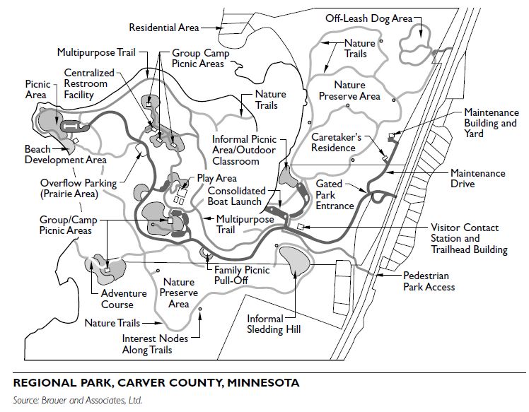
General Characteristics
Development Parameters
The design for regional parks is a reflection of the open-space, recreational, and social needs of the region they serve. The level of development is driven by regional standards and needs.
Not covered in this class...